Why we cannot live without a Telco Cloud, and how does one build one?

There are a more mobile phone connections (~7.9 billion) than the number of humans (~7.7 billion) colonising this planet.

Let me explain.

Clearly, not every person in the world has a mobile device. Here we’re talking about mobile connections that come from people with multiple devices (dual SIMs, tablets) and other integrated devices like cars, and other smart vehicles, and of course the myriad IOT devices. I don’t have to go too far — my electric 2 wheeler has a mobile connection that it uses to cheerfully download the updated firmware version and the software patches every now and then.

While the global population is growing at 1.08% annually, the mobile phone connections are growing at 2.0%. We will very soon be outnumbered by the number of mobile subscriptions, all happily chatting, tweeting and in general sending data over the network. Some of it would need low latency and low jitter, while some may be more tolerant to the delays and jitter.

What’s the big deal with mobile connections growing?

Well, historically most people have used their mobile phones to talk; to catch up on all the gossip on your neighbours and relatives.

Not anymore.

Now, it’s primarily being used to watch video.

And lots of it; both cached and live.

And it will only grow.

Video traffic in mobile networks is forecast to grow by around 34 percent annually up to 2024 to account for nearly three-quarters of mobile data traffic, from approximately 60 percent currently.

Why is the mobile video traffic growing?

The growth is driven by the increase of embedded video in many online applications, growth of video-on-demand (VoD) streaming services in terms of both subscribers and viewing time per subscriber, multiple video sharing platforms, the evolution towards higher screen resolutions on smart devices. All of these factors have been influenced by the increasing penetration of video-capable smart devices.

India had (still has?) the highest average data usage per smartphone at around 9.8 GB per month by the end of 2018.

And the Internet traffic’s not even hit the peak yet.

It will hit the roof once 5G comes in. Will reach dizzying stratospheric heights when mobile content in the Indian vernacular languages comes of age.

India is home to around 19,500 languages or dialects. Every state has its own primary language and which often is alarmingly different from the state bordering it. There is a popular Hindi saying:

Kos-kos par badle paani, chaar kos par baani

The languages spoken in India change every few kilometres, as does the taste of the water.

Currently, most of the mobile content is in few popular Indian languages.

However, thats changing.

How is the Internet traffic related to the number of languages in India?

According to a Sharechat report, 2018 was the year when for the first time internet users in great numbers accessed social media in their regional languages and participated actively in contributing to user generated content in native languages.

A KPMG India and a Google report claims that the Indian language internet users are expected to grow at a CAGR of 18% vs English users at a CAGR of 3%.

This explains a flurry of investments in vernacular content startups in India.

When all these users come online, we are looking at a prodigious growth in the Internet traffic. More specifically, in the user generated traffic, which primarily would be video — again, video that is live or could be cached.

In short, we’re looking at massive quantities of data being shipped at high speeds over the Internet.

And for this to happen, the telco networks need to change.

From the rigid hardware based network to a more agile, elastic, virtualized, cloud based network. The most seismic changes will happen in the service provider network closest to the customer — the edge network. In the Jurassic age, this would have meant more dedicated hardware at the telco edge. However, given the furious rate of innovation, locking into rigid hardware platforms may not be very prudent since the networks will need to support a range of new devices, service types, and use cases. 5G with its enhanced mobile data experience will unleash innovation that’s not possible for most ordinary mortals to imagine today. The networks however need to be ready for that onslaught. They need to be designed to accommodate the agility and the flexibility that is not needed today.

And how do the networks get that agility and flexibility?

I agree with Wally for one.

The telcos will get that flexibility by virtualizing their network functions, and by, uhem, moving it all to the cloud.

Let me explain this.

Every node, every element in a network exists for a reason. It’s there to serve a function (routing, firewall, intrusion detection, etc). All this while we had dedicated, proprietary hardware that was optimized and purpose built to serve that one network function. These physical appliances had to be manually lugged and installed in the networks. I had written about this earlier here and here.

Now, replace this proprietary hardware with a pure software solution that runs on an off-the-shelf x86 based server grade hardware. One could run this software on a bare metal server or inside a virtual machine running on the hypervisor.

Viola, you just “virtualized” the “network function”!

This is your VNF.

So much for the fancy acronym.

The networks get that flexibility and agility by replacing the physical appliances with a telco cloud running the VNFs. By bringing the VNFs closer to their customer’s end devices. By distributing the processing, and management of data to micro datacenters at the periphery of the network, closer to the customer end devices. Think of it as content caching 2.0.

The edge cloud will be the first point of contact and a lot of processing will happen there. The telco giants are pushing what’s known as edge computing: where VNFs run on a telco cloud closer to the end user, thereby cutting the distance to a computer making a given decision. These VNFs, distributed across different parts of a network, run at the “edges” of the network.

Because the VNFs run on virtual machines, one could potentially run several such virtual functions on a single hypervisor. Not only does this save on hardware costs, space and power, it also simplifies the process of wiring together different network functions, as it’s all done virtually within a single device/server. The service function chaining got a lot simpler!

While we can run multiple VNFs on a single server, we can also split the VNFs across different servers to gain additional capacity during demanding periods. The VNFs can scale up, and scale down, dynamically, as the demand ebbs and flows.

This just wasn’t possible in the old world where physical network functions (fancy word for network appliances) were used. The telco operators would usually over-provision the network to optimize around the peak demand.

In the new paradigm we could use artificial intelligence and deep learning algorithms to predict the network demand and spin the VNFs in advance to meet the network demand in advance.

How can machine learning help?

Virtual Network Functions (VNFs) are easy to deploy, update, monitor, and manage. It’s after all just a special workload running on a VM. It takes less than a few seconds to spin a new instance of a VM. 

The number of VNF instances, similar to generic computing resources in cloud, can be easily scaled based on load. Auto-scaling (of resources without human intervention) has been investigated in academia and industry. Prior studies on auto-scaling use measured network traffic load to dynamically react to traffic changes.

There are several papers that explore using a Machine Learning (ML) based approach to perform auto-scaling of VNFs in response to dynamic traffic changes. The ML classifiers learn from past VNF scaling decisions and seasonal/spatial behavior of network traffic load to generate scaling decisions ahead of time. This leads to improved QoS and significant cost savings for the Telco operators.

In a 2017 Heavy Reading survey, most respondents said that AI/ML would become a critical part of their network operations by 2020. AI/ML and Big data technologies would play a pivotal role in making real time decisions when managing virtualized 5G networks. I had briefly written about it here.

Is Telco Cloud the same as a data center?

Oh, the two are different.

Performance is the key in Telco Cloud. The workloads running on the Telco Cloud are extremely sensitive to delay, packet loss and latency. A lot of hard work goes into ensuring that the packet reaches the VNF as soon as it hits the server’s NIC. You dont want the packet to slowly inch upwards through the host’s (its almost always Linux) OS before it finally reaches the VM hosting the VNF.

In a datacenter running regular enterprise workloads, a few milli seconds of delay may still be acceptable. However, on a telco cloud, running a VNF, such a delay can be catastrophic.

Linux, and its networking component is optimized for general purpose computing. This means that achieving high performance networking inside the Linux kernel is not easy, and requires some bit, ok quite a bit, of customizations and hacks to get it past the 50K packets per second limit thats often incorrectly cited as an upper limit for the Linux kernel performance. Routing packets through the kernel may work for the regular data center workloads.

However, the VNFs need something better.

Because the Linux kernel is slow, we need to completely bypass the kernel.

One could start with SR-IOV.

Very simply, with SR-IOV, a VM hosting the VNF has direct access to subset of PCI resources on a physical NIC. With an SR-IOV compliant driver, the VNF can directly DMA (Direct Memory Access) the outgoing packets to the NIC hardware to achieve higher throughput and lower latency. DMA operation from the device to the VM memory does not compromise the safety of underlying hardware. Intel IO Virtualization Technology (vt-d) supports DMA and interrupt remapping and that restricts the NIC hardware to subset of physical memory allocated for a particular VM. No hypervisor interaction is needed except for interrupt processing.

However, there is a problem with SR-IOV.

Since the packet coming from the VNF goes out of the NIC unmodified, the telco operators would need some other HW switch, or some other entity to slap on the VxLAN or the other tunneling headers on top of the data packet so that it can reach the right remote VM. You need a local VTEP that all these packets hit when they come out of the NIC.

Having a VTEP outside complicates the design. The operators would like to push the VTEP into the compute, and have a plain IP fabric that only does IP routing. There was ways to solve this problem as well, but SR-IOV has limitations on potential migration of the VM hosting the VNF from one physical server to another. This is a big problem. If the VM gets locked down, then we lose on the flexibility and the agility that we had spoken of before.

Can something else be used?

Yes.

There’s a bunch of kernel bypass techniques, and I’ll only look at a few.

Intel DPDK (Data Plane Development Kit) has been used in some solutions to bypass the kernel, and then there are new emerging initiatives such as FD.io (Fast Data Input Output) based on VPP (Vector Packet Processing). More will likely emerge in the future.

DPDK and FD.io move networking into Linux user space to address both speed and technology plug-in requirements. Since these are built in the Linux user space, there are no changes in the Linux kernel. This eliminates the extra effort required to convince the Linux kernel community about the usefulness of the patches and their adoption can be accelerated.

DPDK bypasses the Linux kernel and manages the NIC and CPU assignment directly. It uses up some CPU cores for the network processing. It has threads that handle the receiving and processing of packets from the assigned receive queues. They do this in a tight loop, and anything interrupting these threads can cause packets to be dropped. That is why these threads must run on dedicated CPU cores; that is, no other threads — including the various Linux kernel tasks — in the system should run on this core.

Telcos consider this as a “waste” of their CPU cores. The cores that could have run the VNFs have now been hijacked by the DPDK to process packets from the NICs. Its also questioned if we can get a throughput of 100Gbps and beyond with DPDK and other kernel bypass techniques. It might be asinine to dedicate 30 CPU cores in a 32 core server for packet processing, leaving only 2 cores for the VNF.

Looks almost impossible to get 100Gbps+ thats needed for NFV.

Fortunately, no — things are a lot better.

Enter SmartNICs — the brainer cousin of the regular NICs, or rather NICs on steroids. These days there is a lot more brains in the modern NIC – or at least some of them – than we might realize. They take the offloading capabilities to a whole new level. The NIC vendors are packing in a lot of processors in their NIC ASICs to beef up their intelligence. Mellanox’s ConnectX-5 adapter card, which is widely deployed by hyperscalers has six different processors built into it that were designed by Mellanox.

Ok, so these are not CPUs in the normal sense, the ones you and I understand. These are purpose built to allow the NIC to, for instance, look at fields in the incoming packets, look at the IP headers and the Layer 2 headers and look at the outer encapsulated tunnel packets for VXLAN and from that do flow identification and then finally take actions.

This is history repeating itself.

Many many years ago, when dinosaurs still ruled the Earth, Cisco would use a MIPS processor to forward packets in software. And then the asteroid hit the Earth, and Cisco realized that to make the packet routing and forwarding more efficient and for it to scale, they needed custom ASICs, and they started making chips to forward packets.

This is exactly what is now happening in the Telco Cloud space. Open vSwitch was pure software that steered the data between individual virtual machines and routed it, but the performance and scalability was bad that companies started questioning on why some of the processing couldn’t be offloaded to the hardware. Perhaps, down to the NIC if you will. And thats what the latest and the greatest smartNICs do. You can download the OVS rules onto the NIC cards so that you completely bypass the Linux kernel and do all that heavy lifting in hardware.

DPDK and SmartNICs are very interesting and warrants a separate post, which i will do in some time.

So, what is the conclusion?

Aha, i meandered. I often do when I’m very excited.

The Internet traffic is exploding. It’s nowhere near the saturation point, and will increase manifold with 5G and other technologies coming in.

The Telco network can only scale if its virtualized, a’la the telco cloud. Pure hardware based old-style network, especially at the edges, will fail miserably. It will not be able to keep pace with the rapid changes that 5G will bring in. Pure hardware will still rule in the network core. Not at the edge. The edge cloud is where most of the innovation (AI/ML, kernel bypass in software, smartNICs, newer offloading capabilities, etc) will take place.

Telco cloud is possible. We have all the building blocks, today. We have the technology to virtualize, to ship packets at 100-200 Gbps to (and from) the VMs running the VNFs. Imagine the throughput that a rack full of commodity x86 servers, where each does 200Gbps, will get you.

I am very excited about the technology trendlines and the fact that what we’re working on in Nuage Networks is completely inline with where the networking industry is headed.

I am throughly enjoying this joyride. How about you?

Sudden Explosion of Data Centers in India


Something very interesting is happening in the Indian telecom space these days.

The Indian government is considering a new data localisation law that would require all data around Indian citizens to be stored locally, i.e., within Indian borders. It starts with the fintech companies first, and would then bring in the social media and other IOT companies storing data in its ambit. The Reserve Bank of India (RBI) has cheerfully given a deadline to all fintech companies to ensure that the entire data operated by them, is stored in data centers only in India. Ouch.

RBI so far has refused to accept the representations made by the fintech companies to relax the norms. It’s ruled out the option of data mirroring while addressing the arguments of technological hurdles raised by the fintech companies. It’s instead suggested that companies opt for cloud services or private clouds in order to ensure data localization.

So, what’s data localisation? Data localisation is the process localising the citizen’s data to one’s home country for its processing, storage and collection before it goes through the process of being transferred to an international level. It’s done to ensure the country’s data protection and privacy laws. It is based on the concept of data sovereignty that was inspired by Snowden’s revelations that that the US was collecting vast swaths of data not only from American citizens, but from around the world.

This move by India is not unprecedented. Nigeria, Russia, Germany and China already have strict regulations around storing their citizens data locally.

Given the fintech and the digital currency boom in India (largely supported by the Indian government) we are looking at a prodigious amount of very sensitive financial data that would be generated and stored in India. Master card and other payment gateways have already started moving the data to the servers within Indian borders . WhatsApp Pay is unable to launch in India because it’s still not compliant with the Indian data localisation policies. Not surprisingly WhatsApp Pay has agreed, and it will take off as soon as they move all the Indian users data inside the Indian borders.

And to make things more lively, the Government of India is also working on a draft e-commerce law that requires firms to locally store “community data collected by Internet of Things devices in public space” and “data generated by users in India from various sources including e-commerce platforms, social media, search engines, etc.”

The direct consequence of this is a frenzied interest in building massive data centers in India. The chairman of Adani Group in an interview with Bloomberg said that he would invest over $10 billion to set up data centres in India. Meanwhile in Mumbai, Hiranandani real estate group too has thrown its hat in the ring and has not very surprisingly, announced ambitious plans to build — guess what — data centres in India.

Group CEO Darshan Hiranandani sagely says that “It is like building a school or hospital”.

The only difference being that Hiranandani gets a bigger bang for its buck when it builds a data center vis-a-vis building, say, a school or a hospital. The real estate market in India has seen unprecedentedly low returns and many indian real estate developers are at risk of going belly-up as mounting stress in the nation’s credit market dries up funding even for those willing to pay decade-high rates. All reports seem to indicate a moribund growth rate in the housing market.

So, what does Hiranandani, one of India’s biggest real estate company do?

They decide to invest heavily in building data centers. All done under the brand name Yotta. Adani and Hiranandani want to set up Indian data centers in order to prevent what Mukesh Ambani in December last year said, “Data colonization is as bad as the previous forms of colonization. India’s data must be controlled and owned by Indian people — and not by corporates, especially global corporations.”

Dr Niranjan Hiranandani – Founder & Managing Director – Hiranandani Group says, “The Digital India program is one of the key pillars of Prime Minister’s vision of India becoming a 5-trillion Dollar economy by 2025. We envision a huge opportunity with data localization and protection act to be announced soon by the Government of India in order to regulate the data management business.  This will give a big impetus to the data storage business to grow domestically at an exponential pace bringing the paradigm shift to the Indian Economy”.

Somebody clearly has his priorities set right.

There’s a massive explosion in data being generated by connected internet users in India. According to a report by real estate and infrastructure consultancy Cushman and Wakefield, the size of the digital population in India presents a huge potential demand for data centre infrastructure.


Digital data in India was around 40,000 petabytes in 2010; it is likely to shoot up to 2.3 million petabytes by 2020 — twice as fast as the global rate. If India houses all this data, it will become the second-largest investor in the data centre market and the fifth-largest data centre market by 2050, the consultancy has forecast.

And its just not the fintech companies that are rushing to store Indian data locally, the other social media and IOT companies are following suit. China’s ByteDance has announced that they would be building data centers in India. All the data around Indian users was currently stored in third-party data centers in the US and Singapore. It will now be moved to India. It’s only a matter of time, and other social media companies will cave in, and open their data centers in India. The market size and business potential in India is too huge to be risked.

I came up with this partial list of planned and ongoing investments in data centers in India:

  • Microsoft continuing to manage and expand three Azure cloud service data centers in Mumbai, Pune and Chennai
  • IBM’s plans to set up its second data center in India in addition an existing one in Mumbai
  • Google Cloud Platform recently entered India
  • Alibaba Cloud launched in Mumbai in January 2018
  • Amazon Web Services has seen a 60% increase in customers across Mumbai since launch
  • CtrlS has launched a $73 million project in Bangalore and will be adding new centers in Hyderabad and Mumbai within three years
  • GPX Global Systems planning a 16 MW center in Mumbai to be finished Q1 2019
  • The state of Tamil Nadu has completed a $9 million center in Tiruchirappalli to back up government data
  • Netmagic Solutions is spending $175 million to complete centers in Mumbai and Bangalore by the end of April
  • ESDS Software & Nxt Gen Data Center & Cloud Technologies have announced funding & expansion plans in the near to medium term.
  • Ascendas-Singbridge is investing $1 billion on new construction in Chennai, Mumbai, and Hyderabad

So far, no definitive decision around the data localisation policy has been taken and a draft Personal Data Protection Bill has been submitted that recommends setting up a data protection authority and placing restrictions on cross-border data flows. The bill mandates storing one serving copy of all personal data within India. It empowers the central government to classify any sensitive personal data as critical personal data and mandates its storage and processing exclusively in India.

The bill is yet to be cleared by the cabinet but is listed to be tabled in Parliament during the ongoing budget session. Many people believe that the bill will claw through the opposition since there is a very strong lobby behind this.

Independent of what happens with the bill in this particular parliament session, we will, one way or the other, see a massive growth in data centers in India. The amount of data being generated in India is too valuable to be lost, and the Indian government will not want to lose that “oil”.

dt_c120622

Unlike the Dilbert strip above, one needn’t try too hard to make building data centers look like a good investment. Look around, and you’ll see the winds of changing blowing.

Smells like an opportunity to me.

And for anybody else who is in networking and the data center space.

SDN with Big Data Analytics for an Intelligent Network

Software, cloud computing and IOT are rapidly transforming networks in a way, and at a rate, never seen before. With software-as-a-service (SaaS) models, enterprises are moving more and more of their critical applications and data to public and hybrid clouds. Enterprise traffic, that never left the corporate network, is now shifting to the Internet, reaching out to different data centers across the globe. Streaming Video (Netflix, Youtube, Hulu, Amazon) accounts for an absurdly high percentage of traffic in the Internet and content providers have built out vast content distribution networks (CDNs) that overlay the Internet backbone. Higher resolutions (HD and UHD) will increase the traffic further, and by some accounts, will be over 80% of the total network traffic by 2020. More and more businesses are being created that reach their customers exclusively over the Internet (Spotify, Amazon, Safari, Zomato, etc). Real-time voice and video communications are moving to cloud-based delivery and network operators are challenged to deliver these services without impacting user quality of experience. And if this was’nt enough, with the advances being made in IOT, we have more devices than ever, lively communicating and chatting in real time over the Internet.

Security becomes a prime concern as more business critical applications migrate to the cloud. The number of DDOS attacks are only increasing and IOT devices can be compromised by hackers to launch some very lively and innovative attacks. A large scale cyber attack in 2016 used a botnet consisting of a multitude of IoT devices such as printers, camera, web cams, residential network gateways, and even baby monitors causing a major outage that brought down a big chunk of the Internet.

All this traffic goes over service provider networks that were built and designed using devices, protocols and management software from the Jurassic age. The spectacular growth and variability of traffic that is experienced today was not anticipated when these networks were built. There is a dire need to cope with changing traffic patterns and to optimize the use of available network resources at all levels (IP, MPLS and Optical) — we’ll talk about the multi-layer SDN controller that optimizes the IP-Optical layers some other time.

Given these challenges, its imperative that service providers work towards gaining realtime visibility into the network behavior and extract actionable insights needed to react immediately to network anomalies, changing traffic patterns and security threats and alarms.

And this is where big data analytics, like a knight in the shining armour, comes in.

Given the data rates that we are dealing with, and the rate at which traffic volumes and speeds are growing, deep packet inspection at line rate gets ruled out in most parts of the network. There is only so much that one can do with hardware’s brute force approach. Additionally, with most traffic being encrypted, DPI offers limited — no, zero — insight into whats happening in the network.

What can help at the scale that networks run today is streaming telemetry combined with big data analytics. Instead of constantly polling the devices in the network and then reacting to what is learnt, the new age mantra is for these devices to periodically push the relevant statistics to the data collectors, which can analyse this data and act based on that. One can argue that streaming network telemetry may not even require an IETF standard in order to be useful. A standard format like JSON could be used, and it’s up to the collector to parse and interpret the incoming barrage of data. This allows network operators to quickly write dev-ops tools that they can use to closely monitor their network and services. This opens up room for hyper innovation where new-age startups can quickly come up with products that can smartly mine the data from the network and draw rich insights into whats happening that can help the service providers in running their networks smarter and hotter.

Big data analytics entails ingesting, processing and storing exabytes worth of network data over a period of time that can be analysed later for actionable insights. With advances made in streaming analytics, this analysis can also happen in real time as the data comes piping hot from the network. New age scalable stream processors make it possible to fuse data streams to answer more sophisticated queries about the network in real-time.

By correlating data from sources beyond traditional routing and networking equipment (IX router-server views, DNS and CDN logs, firewall logs, billing and call detail records) it is possible for the analytics engine to identify patterns or behaviors that can not be identified by merely sifting through the device logs (collected traditionally using SNMP, syslogs, netflow, sflow, IPFIX, etc). The ability to correlate telemetry data from the network with applications such as Netflix or Youtube or SaaS applications such as an iOS upgrade can provide insights that can never be found with traditional traffic engineering approaches.

I claim that we now have the smarts to avoid the famous iOS7 meltdown that happened when iOS7 was released. Let’s see how:

The analytics engine feeding the controller can identify and correlate iOS updates to a new spike — an anomaly — in the network utilization inside an enterprise. The SDN controller can install more specific flows that will steer all iOS update traffic on a different path in the network. This way the controller can automatically adjust the enterprise customer flows to either (i) provide an improved iOS update experience OR (ii) prevent other enterprise traffic to get affected with the iOS update tsunami.  Advanced IP controllers (and those are being demo’ed to several service providers currently) can steer such traffic across multiple ASes as well.

We recently demo’ed a hierarchical SDN controller to a very big customer in Europe. The SDN controller was used to set up inter-domain IP/MPLS services and it used telemetry feeds to determine the realtime link utilization of the inter-domain links. We used that information to place the inter-domain IP services across multiple ASes — the new services were placed on the least utilized inter-domain link at that instance. The services could be moved around as the link utilization changed. This is very different from how its done today, where the BW utilization is reserved and services are placed based on the hard reservations. IMO, the concept of hard reservations will get obsoleted very soon. Why assume that a VPLS service on a link will take up 1Gbps, when the traffic that it “historically” sends never exceeds 100 Mbps?

The figure below shows the different sources feeding into a typical big data analytics cluster that feeds the output to the SDN controller.

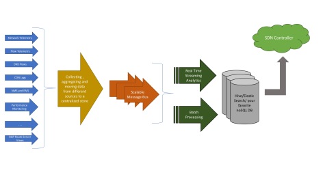
Flow telemetry and network telemetry will help in monitoring the traffic flowing inside the service provider networks. We could use this to gain a deep understanding of what a network looks like during normal operations and how it looks like when an anomaly is present in the network.

If one understands the “normal”, the abnormal can become apparent. What comprises abnormal may vary from network to network and from attack to attack. It could include large traffic spikes from a single source in the network, higher-than-typical traffic “bursts” from several or many devices in the network, or traffic types detected that are not normally sent from a known device type. Once the abnormal has been identified, the attacks can be controlled and eliminated.

Network telemetry will also help in peering analytics to select the most cost-effective peering and transit connections based on current and historic traffic trends. Correlating this data with BGP feeds from route servers can help in visualizing how the traffic flows/shifts from one AS to the other.

Data collected from different sources is fed to a scalable publish/subscribe pipeline that feeds this to the big data analytics platform. Some of this can be fed to a real time streaming analytics platform for deriving rich real time insights from the network. This can then be fed to a machine learning cluster for predictive analytics.

The data is stored in a scalable data lake which can be optimized for complex, multi-dimensional queries that becomes the building block for the SDN controller to do something useful. This data can be coupled with the other data that is being learnt off different sources (syslog records, DNS and CDN logs, IX views, etc) and all this can be processed and transformed into actionable intelligence. For example, this can help service providers understand the amount of Facebook, Netflix, Youtube and Amazon Prime Video traffic thats flowing in their networks. It can help them construct a “heat map” of the most active sources and the sinks. Combine this with anonymized subscriber demographics, and the big data analytics framework can provide high fidelity insights into how the subscribers, applications and the network are correlated.

This level of insight cannot be derived by merely observing the telemetry feeds alone since it is not straightforward to correlate flows with specific applications, services and subscriber end points. The ability to mine data from a panoply of sources (as shown on the left side of the figure above — DNS servers, repositories that can identify servers and end points by owner, geo-location, type and purpose) and being able to correlate them is what differentiates the new age intelligent networks from the ones that exist today.

This level of sophistication can not be achieved without a solid big data analytics framework supporting the SDN controller. The limitless potential of what can be achieved will only unfold as more real deployments start happening in the next few years. We’re living in very interesting times, and I’m waiting with bated breath to see what the future holds and how the networking industry becomes “great again”!

Software defined WAN (SD-WAN) is really about Intelligence ..

Lets admit that most of us in the networking domain know as much about SD-WAN as an average 6th grader on fluid mechanics — which is to say pretty much nothing. We take it as something much grander and exotic than what it really is and are obviously surrounded by friends and well-wishers who wink conspiratorially that they “know it all” and consider themselves on an intellectual high ground to educate us on matters of this rich and riveting biological social interaction. Like most others in that tender and impressionable age, i did get swayed by what i heard and its only later that i was able to sort things out in my head, till it all became somewhat clear.

The proverbial clock’s wound backwards and i experience that feeling of deja-vu each time i read an article on SD-WAN that either extols its virtues or vilifies it as something that has always existed and is being speciously served on a platter dressed up as something that it is not. And like the big boys then, there are men who-know-it-all, who have already written SD-WAN off as something that has always existed and really presents nothing new here. Clearly, i disagree with that view.

I presume, perhaps a trifle rashly, that you are already aware of basic concepts of SDN and NFV (and this) and hence wouldnt waste any more oxygen explaining those.

So what really is the SD-WAN technology and the precise problem that its trying to solve?

SD-WAN is a way of architecting, designing and deploying enterprise WANs using commodity Internet connections in a manner that makes those “magically” appear as a private “MPLS-like” connection. Its the claim that it can appear “MPLS-like” that really peeves the regular-big-mpls-vendors-and-consultants. I will delve into the “MPLS-like” aspect a little later, so please hold on to your sabers till then. What makes the “magic” work is the control plane that implements and enforces the network access policies (VOIP is high priority/low latency/low jitter, big data sync medium priority and all else low priority, no VOIP via Afghanistan, etc) and the data plane that weaves an L2/L3 overlay on top of the existing consumer-grade Internet links (broadband links and in a few cases the LTE/4G connections).

The SD-WAN evangelists want to wean enterprises off their dedicated prohibitively priced private WAN connections (read MPLS circuits) with commodity enterprise broadband links. Philosophically, adding a new branch should just mean shipping a CPE device (perhaps in a virtualized form-factor) that auto-magically dials into a central controller when brought to life. Once thats done and the credentials verified, the branch should just come online (viola!) and should be visible to all the geo-separated branches. Contrast this with the provisioning time (can go as high as a year in some remote locations) and the complexity it takes to get a remote branch online today with MPLS and you will understand why most IT folks have ulcers and are perennially on anti-anxiety/depressant medicines. And btw we’ve not even begun talking about the expenses and long term contracts with the MPLS connections here!

Typically SD-WAN solutions have a central SDN controller which is really a cluster of x86 devices (servers, VMs, containers, take your pick) and hence has computing and analytical horsepower much more than a dedicated HW network device. The controller has complete visibility right from the source all the way till the destination and can constantly analyze traffic and can carve out optimal network paths for applications and individual flows based on the user and application policies. In the first mile the Internet links are either coalesced to form a fatter pipe or are used separately as dictated by the customer policies. The customer traffic is continuously finger-printed and is routed dynamically based on the real time network conditions.

Where most people go wrong is when they believe that SD-WAN solutions lose control over the traffic once it leaves the customer premises or the SD-WAN edge node. Bear in mind that there is nothing in the SD-WAN technology that prevents further control over how the traffic is routed and this could perhaps be one aspect differentiating one SD-WAN offering from the other. Since SD-WAN is an overlay technology you will not have control over each physical hop, but you can surely do something more nuanced given the application and end-to-end network visibility that exists with the controller.

MPLS and SD-WAN !

Its “MPLS-like” in the sense that you can, in most cases, guarantee the available bandwidth and network up time. The central controller can monitor each overlay circuit for loss/jitter/delay and can take corrective actions when routing traffic. Patently enterprise broadband connections in certain geographies dont come with the same level of reliability as MPLS and it behooves upon us to ask ourselves if we need that level of reliability (given the cost that we pay for such connections). An enterprise can always hedge its risks by commissioning a few backup enterprise broadband connections for those rainy days when the primary is out cold. Alternatively, enterprises can go in for a hybrid approach where they maintain a low bandwidth MPLS connection for their mission-critical traffic and use the SD-WAN solution for everything else OR can implement a policy to revert to the MPLS connection when the Internet connections are not working satisfactorily. This can also provide a plausible transition strategy to the enterprises who may not be comfortable switching to SD-WANs given that the technology is still relatively new.

And do note that even MPLS connections go down, so its really not fair to say that SD-WAN solutions stand on tenuous grounds with regard to the reliability. Yes i concede that there are SLAs given with MPLS that just dont exist with regular Internet pipes. However,  one could argue that you can get some bit of extra reliability by throwing in an additional Internet link (with a different provider?) thats only there as a standby. Also note that with service providers now giving fiber connections, the size and the quality of Internet links is only going to improve with time. A large site for instance can aggregate a 1Gbps Google Fiber and a 1Gbps Verizon FIOS connection and can retain a small MPLS connection as the standby. If the enterprise discovers that its MPLS connection is underutilized it can negotiate on pricing or can go with lower MPLS pipe and thereby save on its costs.

I recently read a blog which argued that enterprise broadband promising 350Mbps would mostly give only around 320Mbps on an average. Sure this might be true in a few geographies, but seriously, who cares? Given the cost difference between a broadband connection and an MPLS circuit i will gladly assume that i only had a 300Mbps connection and derive utmost pleasure any time it gives me anything more than that!

The central controller in the SD-WAN technologies amongst other things (analyzing traffic, links) can also continually learn about the customer network conditions and can predict when link qualities will deteriorate and can preemptively reroute traffic before the links start acting up. Given that the controller is monitoring paths end-to-end and is also monitoring and analyzing the traffic emanating from the branch sites there are insights that enterprises can draw that they could have never imagined when using traditional WAN architectures since in that world all connections are really only “dumb pipes”. SD-WAN changes all that — it changes how the enterprise connections and the applications running there are viewed. The WAN architecture is aligned to the application service requirements and its management is greatly simplified. You can implement complex network policies and let the SD-WAN infrastructure sweat on your behalf (HINT: intent driven networking).

So watch out before you disdainfully write off SD-WAN as a technology thats merely replacing your dumb MPLS pipes with the regular Internet connections, since i argue, it can really do a lot more than that. Perhaps a topic worth discussing some other day.

Securing BFD now possible!

Confession Time.

I am guilty of committing several sins. One that egregiously stands out is writing two IETF specs for BFD security (here and here) without considering the impact on the routers and switches implementing those specs. Bear in mind that Bi-directional Forwarding Detection (BFD) is a hard protocol to implement well. Its hard to get into a conversation with engineers working on BFD without a few of them shedding copious quantities of tears on what it took them to avoid those dreaded BFD flaps in scaled setups. They will tell you how they resorted to clever tricks (hacks, if you will) to process BFD packets as fast as they could (plucking them out of order from a shared queue, dedicated tasks picking up BFD packets in the ISR contexts, etc) . In a candid conversation, an ex-employee of a reputed vendor revealed how they stage managed their BFD during a demo to a major customer since they didnt want their BFD to flap while the show (completely scripted) was on. So, long story short — BFD is hard when you start scaling. It just becomes a LOT worse, when you add security on top of it.

The reason BFD is hard is because of the high rate at which packets are sent and consumed. If you miss out a few packets from your neighbor you consider him dead and you bring down your routing adjacency with that neighbor. This causes a lot of bad things (micro-loops, traffic storms, angry phone calls) to happen , least of which trust me, is rerouting the traffic around the “affected” node.

When BFD flaps

The cost of losing BFD packets is very high — so you really want to keep the packet processing minimal, the protocol lean, which is why folks in the BFD WG get a migraine whenever an enthusiastic (though noble) soul mentions a TLV extension to BFD or (even worse) a BFD v2.

Now when you add security, things become a waaaaaaaaaaaaay more complex. Not only do you need to process the packets at a high rate, you also need to compute the SHA or the MD5 digest for each one of those. This becomes difficult when the sessions scale even with hardware assist for BFD.  The current BFD specification for security mandates the digest to be computed for each packet that is sent (you could do something clever with the non-meticulous mode and we’ll talk about it some other day) so the spec is really useless as there is no vendor who can do that at the rate at which BFD packets need to be processed.

This also explains why the BFD specs have not moved further down on the standards track — or simply why they arent RFCs yet.

But there is a need to enhance BFD security, since thats currently the weakest link in the service provider network security. The routing and the signalling protocols have all been enhanced to support stronger cryptographic algorithms and BFD is the only protocol left thats still running without any authentication  (!!!) . I hope this doesnt inspire hackers all around the world to break into the Verizons, the Comcasts and the Tatas. Well, if somebody does, then please pass me a pointer so that i can increase my bandwidth to get all those Pink Floyd bootlegs that i have been scavenging for.

So now, we need  to secure BFD and we are stuck with a proposal that cant be used. Kind of cute, if youre not responsible for running a network.

One way to crack BFD security

The solution to this routing quagmire is however quite simple. I dribbled coffee all over my shirt when i thought of it the first time — checked if I wasnt missing out something obvious and when i was sure that it would hold ground, i pinged one of my co-authors who happened to be thinking on similar lines, and we quickly came up with a draft (after more than a year).

What we’re essentially proposing is this:

Most BFD packets are ping-pong packets carrying same information as was carried in the earlier packets — the payload doesnt change at all (used by most vendors to optimize their implementation — HINT use caching). Only when the state changes, that is, the BFD sessions go Up or Down, or a parameter changes (rarely), does the payload change. Use authentication only when the payload changes and never otherwise. This means that in most cases the packets will be sent in clear-text which can be easily handled as is done today. Only when the state changes, the digest needs to be computed which we know from our extensive experience is a relatively low occurrence event.

This proposal makes it very easy for the vendors to support BFD security, something which folks have been wishing for since long. You can get all the sordid details of our proposal here.

This is the first iteration of the draft and things will change as we move forward. While the current version suggests no changes to the existing BFD protocol, we might going ahead suggest a few changes to the state machine if  that’s what it takes to make the protocol secure. Who said securing BFD was simple ? Its perhaps for this reason that the IETF community still hasnt proposed a solid mechanism for stronger authentication of BFD packets.

You can follow the discussion on the BFD WG mailing list or keep looking at this space for more updates.

Is this draft a reparation for the sins i had mentioned at the beginning of my post earlier?

NFV – CPE vendors MUST evolve!

Customer Premises Equipment (CPE) devices have always been a pain point for the service providers. One, they need to be installed in large large numbers (surely you remember the truck rolls that need to be sent out), and second, and more importantly, they get complex and costlier with time. As services and technology evolve, these need to be replaced with something more uglier and meaner than what existed before. In a large network, managing all the CPEs — right from the configuration, activation, monitoring, upgrading and efficiently adding more services – in itself becomes a full time job (and not the one with utmost satisfaction i must add).

Hate CPEs

ETSI’s Use case #2 describes how the CPE device can be virtualized. The idea is to replace the physical CPEs with all the services it supports on an industry standard server that is and cheaper and easier to manage. Doing this can reduce the number and complexity of the CPE devices that need to be installed at the customer sites.

The jury is still out on the specific functions that can be moved out of the CPE. Clearly, what everybody agrees to is a need for a device that will physically connect the customer to the network. There will hence always be a device at the customer premises. If we can virtualize most of the things that a CPE does, then this device could be a plain L2 switch that takes packets from the customers and pushes those towards the network side.

So what do we gain by CPE virtualization?

You reduce the number of devices deployed at customer premises. Most enterprise customers when adding new services add more devices beyond the access point/demarcation device or NID. If the functions serviced by those devices can be virtualized, then you dont need to add those extra devices.

In residential markets, we can completely remove the set-top boxes (including storage for video recorders) and the layer 3 functions provided by home gateways as these functions can be virtualized (on standard servers driven by highly scalable cloud-based software) , leaving each home with a plain L2 switch. This apparently is already underway as we speak.

Since each site has a vanilla L2 switch, you dont need to replace it till its potent enough to handle the incoming traffic onslaught. Since all the intelligence resides in the standard server, it can easily be replaced/upgraded without involving the dreaded truck rolls.

Truck rolls

Your engineers dont have to visit customer premises for upgrades. Since most of the services are hosted over the cloud, all upgrades happen at the hosting location or the data center. Even if the virtualized services are deployed at the customer premises, you dont have to upgrade each CPE device. Its only the server at the customer premises that needs an upgrade.

Newer services and applications can be easily introduced, since those can be tested out at the hosting location or the data center. You dont have to worry about trying it out on all the different CPE devices. Barrier to entry in the network has suddenly lowered since the legacy CPE equipment doesnt need to be replaced. Also helps avoid vendor lock-in if all CPE devices are plain L2 switches and all the “work” is being done in SW on the standard servers.

Scaling up becomes less of a headache. BGP routers, as they start scaling, run out of control plane memory much before they hit the data plane limits. If the control plane has been virtualized, then its much easier to address this problem vis-a-vis when BGP is running on physical routers.

There are several vendors pushing for CPE virtualization. If you’re a CPE vendor who believes that your services are far too complex to be virtualized, then beware that things are moving very fast in the NFV space. I had earlier posted about how virtual routers can replace the existing harware here. Its fairly easy to imagine CPEs going virtual — from being high end devices to easily commoditized L2 switches! So if you dont evolve fast, then you run the risk of getting extinct!

NFV: Will vRouters ever replace hardware routers?


When i started looking at NFV, i always imagined it being relegated to places in the network that would receive only teeny weeny amount of data traffic since the commodity hardware and software could only handle so much of traffic. I also naively believed that it would be deployed in networks where customers were not uber-sensitive to latency and delay (broadband customers, etc). So if somebody really wanted a loud bang for their buck they had to use specialized hardware to support the network function. You couldnt really use Intel x86-based servers running SW serving customers for whom QoS and QoE were critical and vital. The two examples that leap to my mind are (i) Evolved Packet Core (EPC) functions such as Mobility Management Entity (MME) and BNG environments where the users need to be authorized before they can expect to receive any meaningful services.

While i understood that servers were getting powerful and Intel was doing its bit with its Data Plane Development Kit (DPDK) architecture, it didnt occur to me till recently that we would be seeing servers handling traffic at 10G+ line rate. Vyatta, a Brocade company now, uses vRouters to implement real network functions. Vyatta started with its modest 5400 vRouter that could only handle 1G worth of traffic at the line rate. But then last year it announced 5600 vRouter  that takes advantage of Intel multi-core and DPDK architecture to achieve 10x+ performance. Essentially how DPDK drastically improves the performance is by directly passing the packets from the line card to the code running in the userspace by completely bypassing the high-latency DRAM processing thus speeding up the packet processing. It also supports amongst other things, lockless FIFO implementation  for packet enqueue/dequeue as semaphores and spinlocks are expensive.

The Vyatta 5600 vRouter can be installed on pretty much any x86 based server and can support number of network functions such as dynamic routing, policy-based routing, firewalls, VPN, etc. Vyatta redesigned its software to make use of multiple cores — so while the control plane ran on one core, the data plane was distributed across multiple cores. Using a 4 core processor, they ran control plane on 1 core, and 3 instances of line traffic were handled by the remaining 3 cores.  This way Vyatta was able to handle 10G traffic through a single processor.

Now imagine putting 3-4 such x86 based servers in a network. If (and we look at this in some other blog post) you can split the data traffic equitably, you can achieve close to 30-40G throughput.

Wind River a few weeks ago announced its new accelerated virtual switch (vSwitch) that could deliver 12 million packets per second to guest virtual machines (VMs) using only two processor cores on an industry-standard server platform, in a real-world use case involving bidirectional traffic. 

Many people believe that NFV is best suited to deployed at the edge of the network — basically close to the customers and isnt yet ready for the core or places where the traffic volumes are high or the latency tolerance is low. I agree to this, and covered this aspect in great details here.

What this shows is that its patently possible for virtual routers to run at speeds comparable to regular hardware based routers and can replace them. This augurs well for NFV since it means that it can be deployed in a lot many places in the carrier network than what most skeptics believed till some time back.

NFV and SDN – The death knell for the huge clunky routers?

Last IETF i ran into a couple of hallway discussions where the folks were having a lively debate on whether Network Function Virtualization (NFV) and Software Defined Networking (SDN) will eventually sound the death knell for huge clunky hardware vendors like Cisco, Juniper, Alcatel-Lucent, etc. I was quickly apprised about some Wall Street analyst’s report that projected a significant drop in Cisco’s revenue over the next couple of years as service providers moved to SDN and NFV solutions . I heard claims about how physical routers (that i so lovingly build in AlaLu) will get replaced by virtual routers (vRouters) and other server based software that even small startups could build. The barrier to entry in the service provider markets had suddenly been lowered and the monopoly of the big 3 was being ominously challenged. There was talk about capex spending reduction happening in the service provider networks and how a few operators were holding on to their purchase orders to see how the SDN and NFV story unfurled. There was then a different camp that believed that while SDN and NFV promised several things, it would take time before things got really deployed and started affecting capex spending and OEM’s revenues.

So whats the deal?

Based on my conversation with several folks actively looking into SDN/NFV and a good bit of reading I understand that operators are NOT interested in replacing their edge aggregation and core routers with software driven vRouters. They still want to continue with those huge clunky beasts with full control plane intelligence embedded alongside their  packet pushing data plane. These routers are required to respond to network events in real time (remember FRR?) to prevent outages and slowdowns. Despite all performance improvements the general purpose processors can typically process not more than 2-3 Gbps per core (Intel with DPDK module and APIs for Open Virtual Switch promises better throughput) which is embarrassingly slow when compared to the throughput of 400-600 Gbps thats possible with NPUs and ASICs today. Additionally routers using non-ethernet ports (DSL, PON, Coherent Optical, etc)  cannot be easily virtualized since the general purpose CPUs cannot perform the network functions along with the DSP components required to support these ports.

So while a mobile gateway that essentially forwards packets can be virtualized, it would only make sense to do this where the amount of traffic its handling is relatively small.

So where can we deploy these NFV controlled server based vRouters?

The Provider Edge (PE) routers does several things today, few of which could be easily moved out to be implemented on standard server hardware. ETSI’s NFV Use cases document (case #2)  identifies vPE as a potential NFV use case. The “PE” routers in the MPLS world connects the customer edge (CE) router at the customer premises to the P routers in the provider network. The PE router serves as the service delimiter where it provides L3 VPNs, VPLS, VLL, CDNs and other services to the customers.

The ETSI NFV use-case document (case #2) describes how enterprises are deploying multiple services in branch offices; several of these enterprises use dedicated standalone appliances to provide these services (firewalls, IDS/IPS, WAN optimization, etc), which is “cost prohibitive, inflexible, slow to install and difficult to maintain”.

As a result, many enterprises are looking at outsourcing the virtualization of enterprise CPE (access router) into the operator’s network.

Increased capex and opex pressure is edging enterprises and providers to look at virtualization capabilities made possible by NFV. So, lets look at what all can be virtualized by NFV.

The ETSI NFV use-case document states that “Traditional IP routers  based on custom hardware and software are amongst the most capital-intensive portions of service-provider infrastructure. PE routers run out of control plane resources before they run out of data plane resources and virtualization of control plane functions improves scalability.”

It further states that moving some of the control plane to equivalent functionality implemented in standard commercial servers deploying NFV can result in significant savings.

The figure below gives an idea of the components that can be moved out of the PE router and onto an NFV-powered server.

Network functions/services that can be offloaded from the PE router

If we’re able to push out the functions/services shown in the figure above, the PE router effectively gets reduced to a router thats mainly pushing the packets out and vPE, the device for service delivery. NFV appears to be most effective at the edge of the network where customers are served — this also happens to be mostly ethernet, which works in the favor of NFV since other ports cannot be served as effectively.

Operators believe NFV can be used for mobile packet core functions for 3G and EPC. LTE operators believe that while basic packet pushing functions must still reside in the routers, the other ancillary functions that have been added to the routers over the time are good candidates for NFV. We can keep BRAS, firewalls, IDS, WAN optimizers, and other service functions separate and use the physical router for merely transferring the packets.

Clearly, the vPE can handle many network functions that are currently done by the conventional physical routers. While the PE may still handle pushing the packets, the intelligence for many of the services typically handled by the PE can be moved to vPE. This is a paradigm shift from what the PE routers have been doing all this while. The network functions and services that can be moved to vPE are:

  • Mobile packet core functions for 3G and LTE EPC
  • Firewalls (FW) and IDS/IPS (Intrusion Detection and Intrusion Prevention systems)
  • Deep Packet Inspection (DPI)
  • CDNs (content delivery networks) and caching
  • IP VPNs – control plane to set up the MPLS VPNs
  • VLLs and VPLS – control plane to set up the MPLS VPNs

These functions can be virtualized to run either on the servers under NFV or can be SDN controlled. Where these reside in the network will depend upon the QoS and QoE (Quality of Experience) required by the customers. If latency and speed is an issue, the functions should reside in servers close to the customers. But if latency is not an issue the functions could reside deep in the provider network or a remote data center.

Conclusion

Operators will deploy NFV and SDN, which will impact their buying decisions. Its clear that they will not be replacing their core and  edge aggregation routers with NFV driven software solutions. Instead, NFV will be used at the edge to offload service functions from the HW PE router onto servers with vPE in the NFV environment to deliver new services agilely to end users and generate higher revenue.

There is thus no need for the Ciscos, Junipers and Alalu’s of the world to worry about falling revenues since the NFV powered solutions are not targeting their highest margain businesses — at least not yet!

BFD in the new Avatar


BFDWe all love Bi-directional Forwarding Detection (BFD) and cant possibly imagine our lives without it. We love it so much that we were ready with sabers and daggers drawn when we approached IEEE to let BFD control the individual links inside a LAG — something thats traditionally done by LACP.

Having done that, you would imagine that people would have settled down for a while (after their small victory dance of course) — but no, not the folks in the BFD WG. We are now working on a new enhancement that really takes BFD to the next level.

There isnt anything egregiously wrong or missing per se in BFD today. Its just not very optimal in certain scenarios and we’re trying to plug those holes (and doing our bit to ensure that folks in data comm industry have ample work and remain perennially employed).

Ok, lets not be modest – there are some scenarios where it doesnt work (as we shall see).

So what are we fixing here?

Slow Start

Well for one, BFD takes awfully looooong to bring up the session. Remember BFD starts with sedate timers and then slowly picks up (each side needs to come to an agreement on the rate at which they will send packets) . So it takes a while before BFD can really be used for path/end node liveliness detection. If BFD is being used to validate an MPLS path/LSP then it will take a few additional seconds for BFD to come up because of the LSP ping bootstrapping procedures (RFC 5884).

In certain deployments, this delay is bad and we want to eliminate it. It is expected that some MPLS deployments would require traffic engineered LSPs to be created dynamically, driven by external applications as in Software Defined Networks (SDN). It is operationally critical to ensure that the forwarding paths are up (via BFD) before the applications start utilizing the newly created tunnels. We cant hence wait for BFD to take its time in coming up since the applications are ready to push data down the tunnels. So, something needs to be done to get BFD to come up FAST!

This is an issue in SDN domains where a centralized controller is managing and maintaining the dynamic network. Since the tunnels are being engineered by this centralized entity we want to be really sure that the new tunnel is up before sending traffic down that path. In the absence of additional control protocols (eg. RSVP) we might want to use BFD to ensure that the path is up before using it. Current BFD, with large set up times, can become a bottle neck. If the centralized controller can quickly verify the forwarding path, it can steer the traffic to the traffic engineered tunnel very quickly without adversely affecting the service.

The problem exacerbates as the scale of the network and the number of traffic engineered tunnels increase.

Unidirectional Forwarding Path Validation

The “B” in BFD, stands for “Bi-directional” (in case you missed that). The protocol was originally defined to verify bidirectional connectivity between two nodes. This means that when you run BFD between routers A and B, then both A and B come to know when either router goes down (or when something nasty happens to the link). However, there are many scenarios where only one of the routers is interested in verifying the data plane continuity between the two nodes (e.g., static route using BFD to validate reachability to the next-hop router OR a Unidirectional tunnel using BFD to validate reachability to the egress node). In such cases, validating the reverse direction is not required.

However, traditional BFD requires the other side to maintain the entire BFD state even if its not interested in the liveliness of the remote end.  So if you have “n” routers using a particular gateway, then the gateway has to maintain “n” BFD sessions with all its clients. This is not required and can easily be done away with.

Anycast Addresses

Anycast addressing is used for high availability, fast recovery, load balancing and dispersed deployments where the IGPs direct the traffic to the nearest server(s) within a group of potential servers, all sharing the same Anycast address. BFD as defined today is stateful, and hence cannot work with Anycast addresses.

With the growing need to use Anycast addresses for higher reliability (DNS, multicast, 6to4, etc) there is a need for a BFD variant that can work with Anycast addresses.

BFD Fault Isolation

BFD works in a binary state – it either tells you that the session is UP or its DOWN. In case of failures it doesnt help you identify and localize the fault. Using other tools to isolate the fault may not necessarily work as the OAM packets may not follow the exact same path as the BFD packets (e.g., when ECMP is employed).

There is hence a need for a BFD variant that has some capabilities that can help in fault isolation.

So, where does this lead to?

We have attempted to fix all the issues that i have described above in a new BFD variant that we call the “Seamless BFD” (S-BFD). Its stateless and the receiver (or the reflector) responds with an S-BFD response packet whenever it receives an S-BFD packet from the source. You can imagine this as a ping-pong game between the source and the destination routers. The source (or the client in S-BFD speak) wants to check if the path to the destination (or the Reflector in S-BFD speak) is UP or the reflector is UP and sends an S-BFD “ping” packet. The Reflector upon receiving this, responds with a S-BFD “Pong” packet.  The client upon receiving the “Pong” knows that the Reflector is alive and starts using the path.

Each Reflector selects a well known “Discriminator” that all the other devices in the network know about. This can be statically configured, or a routing protocol can be used to flood/distribute this information. We could use OSPF/IS-IS within an AS and BGP across the ASes. Any clinet that wants to send an S-BFD packet to this Reflector (or a server if it helps) sends the S-BFD packet with the peer’s Discriminator value.

A reflector receiving an S-BFD packet with its own Discriminator value responds with a S-BFD packet. It must NOT transmit any BFD packet based on a local timer expiration.

A router can also advertise more than one Discriminator value for others to use. In such cases it should accept all S-BFD packets addressed to any of those Discriminator values. Why would somebody do that?

You could, if you want to implement some sort of redundancy. A node could choose to terminate S-BFD packets with different Discriminator values on different line cards for load distribution (works for architectures where a BFD controller in HW resides on a line card). Two nodes can now have multiple S-BFD sessions between them (similar to micro-BFD sessions that we have defined for the LAG in RFC 7130) — where each terminates on a different line card (demuxed using different Discriminator values). The aggregate BFD session will  only go down when all the component S-BFD sessions go down. Hence the aggregate BFD session between the two nodes will remain alive as long as there at least one component S-BFD session alive. This is another use case that can be added to S-BFD btw!

This helps in the SDN environments where you want to verify the forwarding path before actually using it. With S-BFD you no longer need to wait for the session to come up. The centralized controller can quickly use S-BFD to determine if the path is up. If the originating node receives an S-BFD response from the destination then it knows that the end point is alive and this information can be passed to the controller.

Similarly applications in the SDN environments can quickly send a S-BFD packet to the destination. If they receive an S-BFD response then they know that the path can be used.

This also alleviates the issue of maintaining redundant BFD sesssion states on the servers since they only need to respond with S-BFD packets.

Authentication becomes a slight challenge since the reflector is not keeping track of the crypto sequence numbers (remember the point was to make it stateless!). However, this isnt an insurmountable problem and can be fixed.

For more sordid details refer to the IETF draft in the BFD WG which explains the Seamless BFD protocol and another one with the use-cases. I have not covered all use cases for Seamless BFD (S-BFD) and we have a few more described there in the use-case document.

iOS7’s impact on networks worldwide

Apple releases an iOS update and the networks all across the world witness a spike of almost 100% in the average traffic that they receive. Apple delivers its content using Akamai, which allegedly handles 20% of world’s total web traffic. Akamai is thus in a unique position to provide a view of whats happening on the web, at any given instant in time. Akamai logs clearly show an over all increase in Internet traffic and the hotspots in Europe soon after Apple released its iOS7.

Akamai
Akamai showing traffic hotspot in Europe

Most service providers saw Akami and Limelight traffic up by an average of 300-700% immediately after iOS7 was released.

Being an Android user myself, i found iOS7’s release with the massive increase in the Internet traffic reported all over the world quite insidious. Honestly, i was a trifle concerned with what iOS7 was internally doing to result this.

It turned out to be quite an anti-climax when i realized that the spurt in network traffic was just because of Apple devices upgrading to the newer iOS. The iOS7 upgrade for the phones is around 900MB, and that for the ipads is around 1.2GB. Given that there are quite a few of these devices out there, one only needs to multiply this with the upgrade size to realize the traffic volumes that service providers all across the world are grappling with.

Its well known that Apple fans dont want to wait before they go in for an upgrade. The iOS7 adoption rate has been the highest ever for any platform (beating their own iOS6 rate, which was in itself phenomenal in all respects). Its claimed that within two days of its release, iOS7 is already running on more than half of all Apple devices out there (which btw is already quite high).

Google is perplexed with how it can improve the miserably low adoption rate for their Android OS.  This seems to stem from the fact that most Android devices just do not receive updates in a timely manner and the ones that do, only go for an update roughly six months after a new version is released.

Jelly Bean (the latest version of Android) currently is on a fewer Android devices than iOS 7 on iOS devices. This may not seem mind boggling, until you realize that iOS 7 has only been out for only 5 days (as of this post) whereas Android Jelly Bean was been around since a little more than a year and half.

iOS’s high adoption rate is a headache for several service providers since, lets face it, all of them oversubscribe their access links. This is done by design, since its assumed that not everyone would demand full bandwidth usage at the same time. Usually it works well, sometimes it doesnt, as we’ll just see.

Most homes have multiple iOS devices, so this translates to each household doing 5-6 GB worth of iOS updates in a single day. Multiply this by thousands and you’ll see the volume of traffic each provider sees around the week whenever an iOS  is released.

Having a CDN which is caching the iOS7 update, would definitely help in any large deployment. What could, suggest some people, also help is if each one of these Apple “i” devices advertise an “iOS update available” locally and other “i” devices merely downloaded the update from there, as long as the signature is valid (all images are signed).

This at the very least  can improve the user experience (no more facebook/twitter updates on how slow their iOS upgrade was) and can potentially help in avoiding clogging the Internet tubes.

Few service providers are furious with Apple as they see their customers complaining that their network/Internet access is slow. There is a camp that thinks its pretty dumb on Apple’s part to make their OS update available globally on the same day — Microsoft and others have a strategy where they provide incremental downloads. Others suggest that Apple should do this on weekends, when traffic volumes are low.  I strongly disagree with this line of reasoning and believe its parochial to call on a war on Apple — remember, iOS updates are user pulls, not Apple pushes. Its the Operators who should update their infrastructure to gracefully handle such events — today its an iOS7 release, tomorrow it could be something else (Obama in a political sex scandal?). If this means getting fatter pipes, or talking to CDN vendors to put caches in their networks or putting up their own caches, then this ought to be done. If they do not/cannot have an CDN cache then they could explore connecting to an Internet Exchange (IX) that does. IX peering, i am told, is not prohibitively expensive in most countries.

Ben quite succinctly sums it up on a nanog mailing list, “Your (the service provider) user is paying you to push packets. If that’s causing you a problem, you either need to review your commercial structure (i.e. charge people more) or your technical network design. Face the facts, what with everyone jumping on the “cloud” bandwagon, the future is only going to see you pushing more packets, not less !  So if you can’t stand the heat, get out of the kitchen (or the xSP industry).”

How bad is the OSPF vulnerability exposed by Black Hat?

ddos-attack

I was asked a few weeks ago by our field engineers to provide a fix for the OSPF vulnerability exposed by Black Hat last month. Prima facie there appeared nothing new in this attack as everyone knows that OSPF (or ISIS) networks can be brought down by insider attacks. This isnt the first time that OSPF vulnerability has been announced at Black Hat. Way back in 2011 Gabi  Nakibly, the researcher at Israel’s Electronic Warfare Research and Simulation Center, had demonstrated how OSPF could be brought down using insider attacks.  Folks were not impressed, as anybody who had access to one of the routers could launch attacks on the routing infrastructure. So it was with certain skepticism that i started looking at yet another OSPF vulnerability exposed by Gabi, again at Black Hat. Its only when i started delving deep into the attack vector that the real scale of the attack dawned on me. This attack evades OSPF’s natural fight back mechanism against malacious LSAs which makes it a bit more insidious than the other attacks reported so far.

I exchanged a few emails with Gabi when i heard about his latest exposé. I wanted to understand how this attack was really different from the numerous other insider attacks that have been published in the past. Insider attacks are not very interesting, really. Well, if you were careless enough to let somebody access your trusted router, or somebody was smart enough to masquerade as one of your routers and was able to inject malicious LSAs then the least that you can expect is a little turbulence in your routing infrastructure. However, this attack stands apart from the others as we shall soon see.

OSPF (and ISIS too) has a natural fight back mechanism against any malacious LSA that has been injected in a network. When an OSPF router receives an LSA that lists that router as the originating router (referred to as a self-originated LSA) it looks at the contents of the LSA (just in case you didnt realize this). If the received LSA looks newer than the LSA that this router had last originated, the router advances the LSA’s LS sequence number one past the received LS sequence number and originates a new instance of this LSA. In case its not interested in this LSA, it flushes the LSA by originating a new LSA with age set to MaxAge.

All other routers in the network now update their LS database with this new instance and the malacious LSA effectively gets purged from the network. Viola,its that simple!

As a result of this, the attacker can only flood malacious LSAs inside the network till the router that the malacious LSA purports to come from (victim router) receives a copy. As soon as this router floods an updated copy, it doesnt take long for other routers in the network to update their LS DB as well – the flooding process is very efficient in disseminating information since network diameters are typically not huge, and yes, packets travel with the speed of light. Did you know that?

In the attack that Gabi described, the victim router does not recognize the malacious LSA as its own and thus never attempts at refreshing it. As a result the malicious LSA remains stealthily hidden in the routing domain and can go undetected for a really long time. Thus by controlling a single router inside an AS (the one that will flood the malacious LSA), an attacker can gain control over the entire routing domain. In fact, an attacker need not even gain control of an entire router inside the AS.  Its enough if it can somehow inject the malacious LSAs over a link such that one of the OSPF routers in the network accept this. In the media release, Black Hat claimed ” The new attack allows an attacker that owns just a single router within an AS to effectively own the routing tables of ALL the routers in that AS without actually owning the routers themselves. This may be utilized to induce routing loops, network cuts or longer routes in order to facilitate DoS of the routing domain or to gain access to information flows which otherwise the attacker had no access to.

So what is this attack?

Lets start by looking at what the LS header looks like.

LS Header

In this attack we are only interested in the two fields, the Link State ID and the Advertising Router, in the LS Header. In the context of a Router LSA, the Link State ID identifies the router whose links are listed in the LSA. Its always populated with the router ID of that router.  The Advertising Router field identifies the router that initially advertised (originated) the LSA. The OSPF spec dictates that only a router itself can originate its own LSA (i.e. no router is expected to originate a LSA on behalf of other routers), therefore in Router LSAs the two fields – ‘Link State ID’ and ‘Advertising Router’ – must have the exact same value. However, the OSPF spec does not specify a check to verify this equality on Router LSA reception.

Unlike several other IETF standards, the OSPF spec is very detailed, leaving little room for any ambiguity in interpreting and implementing the standard. This is usually good as it results in interoperable implementations where everybody does the right thing. The flip side however is that since everybody follows the spec to the tittle, a potential bug or an omission in the standard, would very likely affect several vendor implementations.

This attack exploits a potential omission (or a bug if you will) in the standard where it does not mandate that the receiving router verifies that the Link State ID and the Advertising Router fields in the Router LSA are the exact same value.

This attack sends malacious Router LSAs with two different values in the LS header. The Link State ID carries the Router ID of the router that is being attacked (the victim) and the Advertising Router is set to some different (any) value.

When the victim receives the malacious Router LSA, it does not refresh this LSA as it doesnt recognize this as its own self generated LSA. This is because the OSPF spec clearly says in Sec 13.4 that “A self-originated LSA is detected when either 1) The LSA’s Advertising Router is equal to the router’s own Router ID or 2) the LSA is a network LSA .. “.

This means that OSPF’s natural fight back mechanism is NOT triggered by the victim router as long as the field ‘Advertising Router’ of a LSA is NOT equal to the victim’s Router ID. This is true even if the ‘Link State ID’ of that LSA is equal to the victim’s Router ID. Going further it means no LSA refresh is triggered even if the malacious LSA claims to describe the links of the victim router!

When this LSA is flooded all the routers accept and install this LSA in their LS database. This exists along side the valid LSA originated by the victim router. Thus each router in the network now has two Router LSAs for the victim router – the first that was genuinely originated by the victim router and the second that has been inserted by the attacker.

When computing the shortest path first algorithm, the OSPF spec in Sec 16.1 requires implementations to pick up the LSA from the LS DB by doing a lookup “based on the Vertex ID“. The Vertex ID refers to the Link State ID field in the Router LSAs. This means that when computing SPF, routers only identify the LSAs based on their Link State ID. This creates an ambiguity on which LSA will be picked up from the LS database. Will it be the genuine one originated by the victim router or will it be the malacious LSA injected by the attacker? The answer depends on how the data structures for LS DB lookup have been implemented in the vendor’s routers. Ones that pick up the wrong LSA will be susceptible to the attack. The ones that dont, would be oblivious to the malacious LSA sitting in their LSA DBs.

Most router implementations are vulnerable to this attack since nobody expects the scenario where multiple LSAs with the same Link State ID will exist in the LS DB. It turns out that at least 3 major router vendors (Cisco, Juniper and Alcatel-Lucent) have already released advisories and announced fixes/patches that fixes this issue. The fix for 7210 would be out soon ..

Once again, the attacker does not need to have an OSPF adjacency to inject the forged LSAs.

Doing this is not as difficult as we might think it is. There is no need for the attacker to access the LS DB sequence number – all it needs to do is to send an LSA with a reasonably high sequence number, say something like MAX_SEQUENCE – 1 to get this LSA accepted.

The attack can also be performed without complete information about the OSPF topology. But, this is highly dependent on the attack scenario and what piece of false information the attacker wishes to advertise on behalf of the victim. For example, if the attacker wishes to disconnect the victim router from the OSPF topology then merely sending an empty LSA without knowing the OSPF topology in advance would also work. In the worst case, the attacker can also get partial information on the OSPF topology by using trace routes, etc. This way the attacker can construct LSAs that look very close to what has been originally advertised by the victim router, making it all the more difficult to suspect that such LSAs exist in the network.

DNS poisoned for LinkedIn. Affects us? Sure, it does.

linkedin

If you were unable to access LinkedIn for almost the entire day earlier this week, then you can take solace in the fact that you were not the only one, not able to. Almost half the world shared your misery where all attempts to access LinkedIn (and several other websites) went awry. This purportedly happened because  a bunch of hackers decided to poison the DNS entries for LinkedIn and some other well known websites (fidelity.com being another).

Before we delve into the sordid details of this particular incident lets quickly take a look at how DNS works.

Whenever we access linkedin.com, our computer must resolve this human-readable address “linkedin.com” into a computer-readable IP address like “216.52.242.86″ thats hosting this website. It does this by requesting a DNS server to return an IP address that can be used. The DNS server responds with one or more IP addresses with which you can reach linkedin.com. Your computer then connects to that IP address.

So where is this DNS server located that i just spoke about?

This DNS server lies with your Internet service provider, which caches information from other DNS servers.  The router that we have at home also functions as a DNS server, which caches information from the ISP’s DNS servers — this is done  so that we dont have to perform a DNS lookup each time we have to access a website for which we have already resolved the IP address.

Now that we know the basics, lets see what DNS poisoning is?

A DNS cache is said to be poisoned if it contains an invalid entry. For example, if an attack “somehow” gains control of a DNS server and changes some of the information on it — it could for instance say that citibank.com actually points to an IP address the attacker owns — that DNS server whenever requested to resolve citibank.com would tell its users to look for citibank.com at the wrong address. The attacker’s address could potentially contain some sort of malicious phishing website, which could resemble the original citibank.com or could simply be used to drop all traffic. The latter is done when ISPs want to block all access to a particular website. China typically does it for lot of websites — its called the Great Firewall of China.  There are multiple techniques which China employs to implement their censorship and one of them is DNS poisoning (more here).

Wildfire

DNS poisoning spreads like wild fire because of how it works.  Clearly Internet service providers cannot hold information about all websites in their DNS caches – they get their DNS information from other DNS servers. Now assume, that they are getting their DNS information from a compromised server. The poisoned DNS entry or entries will spread to the Internet service providers and get cached there. It will then spread to other ISPs that get information from this DNS server. And it wouldnt stop at this, it would spread to routers at campuses, homes and the DNS caches on individual user computers. So everybody who requests for the DNS resolution of the hijacked website will receive an incorrect response and will forward traffic to the address specified by the attacker.

LinkedIn.com and a number of other organizations have registered their domain names with Network Solutions. For some inexplicable reason their DNS nameservers were replaced with nameservers at ztomy.com. The nameservers at ztomy.com were configured to reply to DNS requests for the affected domains with IP addresses in the range 204.11.56.0/24. This address range is belongs to confluence networks, so all traffic bound to LinkedIn was re-routed to a networks hosted by confluence networks.

But what caused the name servers to be replaced?

According to Network Solutions (NS), they were hit by a distributed denial-of-service (DDOS) attack on night of 19/06. This is certainly is plausible since Network Solutions, being the original registrar for .com, .net, and .org domain names, is certainly an attractive target for attackers. Most of you would remember the (in)famous August 2009 NS server breach which allegedly led to the exposure of names, addresses, and credit card numbers of more than 500,000 people who made purchases on web sites hosted by the NS.

A spokesperson from Network Solutions had the following to say regarding the DNS poisoning issue:

“In the process of resolving a Distributed Denial of Service (DDoS) incident on Wednesday night, the websites of a small number of Network Solutions customers were inadvertently affected for up to several hours.”

They have reassured customers that no confidential data has been compromised as a result of the incident.

The jury meanwhile, is still out on whether this was a configuration error or a coordinated DNS attack on Network Solutions.

Regardless of what it was, the fact is that enormous amount of  LinkedIn traffic was redirected to some other network. This is should make all of us very nervous since LinkedIn does not use Secure Socket Layer (SSL), which means that all communication between you and LinkedIn goes in plaintext — leaving you vulnerable to eavesdropping and man-in-the-middle attacks. If an attacker is able to intercept all data being sent between a browser and a web server they can see and use that information. In this event all traffic bound to LinkedIn was diverted to IP addresses owned by Confluence Networks.

This isnt the first time LinkedIn has compromised the security of its users. Earlier in June 2012, nearly 6.5 million encrypted passwords were compromised when they were dumped onto a Russian hacker forum. Its around this time that a team of mobile security researchers discovered that LinkedIn’s mobile app for iOS was transmitting information about calendar entries made on that app, including sensitive information like meeting locations and passwords, back to LinkedIn’s servers without users’ knowledge.

Not only is this a clear violation of their user’s privacy (which is a different discussion btw) but is also extremely dangerous if this data transfer is not being done securely, as this would leave LinkedIn users very vulnerable to eavesdropping attacks.

So when the DNS entry for LinkedIn was poisoned we know that all our confidential information was diverted to unknown servers that can mine that data in whatever manner they find most amusing. I just hope that you didnt have any confidential data plugged into your LinkedIn iOS app, as somebody somewhere may just be reading all that as you read this blog post.

Why do we need specialized switches in Data Centers?

data center

Whats the big deal about Data centers and why do they need special routers and switches anyway? Why cant they use the existing switches that folks use in their back offices or service providers in their networks. What’s so special, really, about a bunch of servers that need Internet connectivity, huh?

Working in the metro Ethernet space all my life I wasn’t sure if I really understood the hype and the reason why Data centers required specialized HW.

It’s only once I started reading about Data centers and how they work and what they’re supposed to do that I was able to appreciate their need for specialized HW – and why the existing products may not be cut for them.

In the world of Wall Street, milliseconds can mean billions of dollars. Really, am not kidding here. Packets carrying Wall Street transactions get delivered to the switch and are then forwarded to the server in the Data Center. There they ride up the protocol stack to the application that executes the trade. The commit message then has to go back down the stack and then be sent over the wire to the switch. The switch does a lookup in its forwarding tables and sends it out on an egress destination port.

One of the things that would differentiate one Data Center switch from the other would be the time it takes for the switch to process the incoming packet, the amount and the nature of queuing that happens (which directly affects the latency), the serialization delays at the ingress and egress, and other factors that can contribute to adding a few microseconds to each packet processing (or transaction in Wall Street speak).

So is adding a few microseconds really a big deal?

Oh Yes, you bet it is – especially in the big bad world of Wall Street.

wall street

You only need to google for “high-frequency trading” and you would understand why it’s the suddenly become one of the most talked about thing in the Wall Street.

Lets see how shaving off a few microseconds can help?

A Mutual Fund house places an order to purchase 100000 shares of a company ABC that’s currently going at $10. NASDAQ (or some other exchange) could offer a few selected high frequency traders a peek into the incoming orders for 30 milliseconds or so (this is illegal, but there are loopholes in the system). The high frequency trader, knows that a purchase order for 100000 shares of ABC is coming and immediately picks up all the available shares at $10. After a few seconds, the Mutual Fund house order hits the market place and the high frequency trader sells their shares at $10.50, pocketing $50000 from a single transaction. Now, multiply this by the average number of transactions that typically take place in an Exchange and you would you arrive at the staggering amount of $$$ that’s at stake here.

Its thus imperative that the high speed computers that are doing all the number crunching have supporting network infrastructure that can help them in making the kill. Lower network latency and increased throughput means faster and better profits for the trading companies.

Firms using high frequency trading earned over $21 billion in profits last year. The TABB Group estimates that a 5 millisecond delay in transmitting an automatic trade can cost a broker 1% of its flow; which could be worth $4 million in revenues per millisecond. According to Reuters, trading a stock is now far faster than a blink of an eye or the speed of a lightning strike.

In fact several high frequency traders house their systems as close as possible to the exchanges to minimize the latency in executing their orders.

There are also other environments where low latency is desirable. Environments such as computer animation studios that may spend 80 to 90 hours rendering a single frame for a 3D movie, or scientific compute server farms (for Computational Fluid Dynamics) that might involve tens of thousands of compute cores. If the network is the bottleneck within those massive computer arrays, the overall performance is affected.

The Data centers thus patently need switches that have extremely extremely low latency in forwarding packets.

So what are the other things that the Data center switches must support – and which may not be available in ordinary switches?

Micro-bursting often happens in Data Centers, wherein the buffers overrun and the switches drop packets. The problem is that these micro-bursts happen often at microsecond intervals, so the switches may not report them. A good Data Center switch will absorb the micro-burst and forward the packets without dropping ’em.

Data centers as we just saw are designed for critical systems that require high availability. This means redundant power, efficient cooling, secure access, ideally no down time, and a whole lot of other things, but most of all, it means no single points of failure.

Every device in a data center should have dual power supplies, and each one of those power supplies should be fed from independent power feeds. The power supplies are sized such that the device operates with only power path. All devices in a data center should have front-to-back airflow, or ideally, airflow that can be configured front to back or back to front. Thermal guidelines for Data Centers is a science by itself and there is more than petabytes of information available on the net on how this needs to be effectively done.

All devices in a data center should support the means to upgrade, replace, or shut down any single chassis at any time without interruption to meet the hard Service Level Agreements (SLAs). In-Service Software Upgrades (ISSU) should ideally be available, but this can be circumvented by properly distributing load to allow meeting the prior requirement. Data center devices should offer robust hardware, even NEBS compliance where required, and robust software to match.

This isnt the most exhaustive list of the things required out of switches deployed in Data Centers, and only serves to give a hint of whats needed there.

Oh and btw, I must finish this post and rush to place an order on NASDAQ before some high frequency trader preempts me and books all the profits!

OpenFlow, Controllers – Whats missing in Routing Protocols today?

openflowThere is a lot of hype around OpenFlow as a technology and as a protocol these days. Few envision this to be the most exciting innovation in the networking industry after the vaccum tubes, diodes and transistors were miniaturized to form integrated circuits.  This is obviously an exaggeration, but you get the drift, right?

The idea in itself is quite radical. It changes the classical IP forwarding model from one where all decisions are distributed to one where there is a centralized beast – the controller – that takes the forwarding decisions and pushes that state to all the devices (could be routers, switches, WiFi access points, remote access devices such as CPEs) in the network.

Before we get into the details, let’s look at the main components – the Management, Control and the Forwarding (Data) plane – of a networking device. The Management plane is used to manage (CLI, loading firmware, etc) and monitor the device through its connection to the network and also coordinates functions between the Control and the Forwarding plane. Examples of protocols processed in the management plane are SNMP, Telnet, HTTP, Secure HTTP (HTTPS), and SSH.

The Forwarding plane is responsible for forwarding frames – it receives frames from an ingress port, processes them, and sends those out on an egress port based on what’s programmed in the forwarding tables. The Control plane gathers and maintains network topology information, and passes it to the forwarding plane so that it knows where to forward the received frames. It’s in here that we run OSPF, LDP, BGP, STP, TRILL, etc – basically, whatever it takes us to program the forwarding tables.

Routing Protocols gather information about all the devices and the routes in the network and populate the Routing Information Base (RIB) with that information. The RIB then selects the best route from all the routing protocols and populates the forwarding tables – and Routing thus becomes Forwarding.

So far, so good.

The question that keeps coming up is whether our routing protocols are good enough? Are ISIS, OSPF, BGP, STP, etc the only protocols that we can use today to map the paths in the network? Are there other, better options – Can we do better than what we have today?

Note that these protocols were designed more than 20 years ago (STP was invented in 1985 and the first version of OSPF in 1989) with the mathematics that goes in behind these protocols even further. The code that we have running in our networks is highly reliable, practical, proven to be scalable – and it works. So, the question before us is – Are there other, alternate, efficient ways to program the network?

Lets start with what’s good in the Routing Protocols today.

They are reliable – We’ve had them since last 20+ years. They have proven themselves to be workable. The code that we use to run them has proven itself to be reliable. There wouldn’t be an Internet if these protocols weren’t working.

They are deterministic in that we know and understand them and are highly predictable – we have experience with them. So we know that when we configure OSPF, what exactly will it end up doing and how exactly will it work – there are no surprises.

Also what’s important about today’s protocols are that they are self healing. In a network where there are multiple paths between the source and the destination, a loss of an interface or a device causes the network to self heal. It will autonomously discover alternate paths and will begin to forward frames along the secondary path. While this may not necessarily be the best path, the frames will get delivered.

We can also say that today’s protocols are scalable.  BGP certainly has proven itself to run at the Internet’s scale with extraordinarily large number of routes. ISIS has as per the local folklore proven to be more scalable than OSPF. Trust me when i say that the scalability aspect is not the limitation of the protocol, but is rather the limitation of perhaps the implementation. More on this here.

And like everything else in the world, there are certain things that are not so good.

Routing Protocols work under the idea that if you have a room full of people and you want them to agree on something then they must speak the same language. This means that if we’re running OSPFv3, then all the devices in the network must run the exact same version of OSPFv3 and must understand the same thing. This means that if you throw in a lot of different devices with varying capabilities in the network then they must all support OSPFv3 if they want to be heard.

Most of the protocols are change resistant, i.e., we find it very difficult to extend OSPFv2 to say introduce newer types of LSAs. We find it difficult to make enhancements to STP to make it better, faster – more scalable, to add more features. Nobody wants to radically change the design of these protocols.

Another argument that’s often discussed is that the metrics used by these protocols are really not good enough. BGP for example considers the entire AS as one hop. In OSPF and ISIS, the metrics are a function of the BW of the link. But is BW really the best way to calculate a metric of an interface to feed in to the computation to select the best path?

When OSPF and all the routing protocols that we use today were designed and built they were never designed to forward data packets while they were still re-converging. They were designed to drop data as that was the right thing to do at that time because the mathematical computation/algorithms took long enough and it was more important to avoid loops by dropping packets.  To cite an example, when OSPF comes up, it installs the routes only after it has exchanged the entire LSDB with its neighbors and has reached a FULL state. Given the volume of ancillary data that OSPF today exchanges via Opaque LSAs this design is an over-kill and folks at IETF are already working on addressing this.

We also have poor multipath ability with our current protocols today. We can load balance between multiple interfaces, but we have problems with the return path which does not necessarily come back the way you wanted. We work around that to some extent by network designs that adapt to that.

Current routing protocols forward data based on destination address only. We send traffic to 192.168.1.1 but we don’t care where it came from. In truth as networks get more complex and applications get more sophisticated, we need a way to route by source as well by destination. We need to be able to do more sophisticated forwarding. Is it just enough to send an envelope by writing somebody’s address on an envelope and putting it in a post box and letting it go in the hope that it gets there? Shouldn’t it say that Hey this message is from the electricity deptt. That can go at a lower priority than say a birthday card from grandma that goes at a higher priority. They all go to the same address but do we want to treat them with the same priority?

So the question is that are our current protocols good enough – The answer is of course Yes, but they do have some weaknesses and that’s the part which has been driving the next generation of networking and a part of which is where OpenFlow comes in ..

If we want to replace the Routing protocols (OSPF, STP, LDP, RSVP-TE, etc) then we need something to replace those with. We’ve seen that Routing protocols have only one purpose for their existence, and that’s to update the forwarding tables in the networking devices. The SW that runs the whole system today is reasonably complex, i.e., SW like OSPF, LDP, BGP, multicast is all sitting inside the SW in an attempt to load the data into the forwarding tables. So a reasonably complex layer of Control Plane is sitting inside each device in the network to load the correct data into the forwarding tables so that correct forwarding decisions are taken.

Now imagine for a moment that we can replace all this Control Plane with some central controller that can update the forwarding tables on all the devices in the network. This is essentially the OpenFlow idea, or the OpenFlow model.

In the OpenFlow model there is an OpenFlow controller that sends the Forwarding table data to the OpenFlow client in each device. The device firmware then loads that into the forwarding path. So now we’ve taken all that complexity around the Control Plane in the networking device and replaced it with a simple client that merely receives and processes data from the Controller. The OpenFlow controller loads data directly into the OpenFlow client which then loads it directly into the FIB. In this situation the only SW in the device is the chip firmware to load the data into the FIB or TCAM memories and to run the simple device management functions, the CLI, to run the flash and monitor the system environmentals. All the complexity around generating the forwarding table has been abstracted away into an external controller. Now its also possible that the device can still maintain the complex Control Plane and have OpenFlow support. OpenFlow in such cases would load data into the FIBs in addition to the RIB that’s maintained by the Control Plane.

The Networking OS would change a little to handle all device operations such as Boot, Flash, Memory Management, OpenFlow protocol handler, SNMP agent, etc. This device will have no OSPF, ISIS,RSVP or Multicast – none of the complex protocols running. Typically, routers spend close to 30+% of CPU cycles doing topology discovery. If this information is already available in some central server, then this frees up significant CPU cycles on all routers in the network. There will also be no code bloat – we will only keep what we need on the devices. Clearly, smaller the code running on the devices, lesser is the bugs, resources required to maintain it – all translating into lower cost.

If we have a controller that’s dumping data into the FIB of a network device then it’s a piece of SW – its an application. It’s a SW program that sits on a computer somewhere. It could be an appliance, a virtual machine (VM) or could reside somewhere on a router. The controller needs to have connectivity to all the networking devices so that it can write out, send the FIB updates to all devices. And it would need to receive data back from the devices. It is envisioned that the controller would build a topology of the network in memory and run some algorithm to decide how the forwarding tables should be programmed in each networking device. Once the algorithm has been executed across the network topology then it could dispatch topology updates to the forwarding tables using OpenFlow.

OpenFlow is an API and a protocol which decides how to map the FIB entries out of the controller and into the device. In this sense a controller is, if we look back at what we understand today, very similar to Stack Master in Cisco. So if one has 5 switches in a stack then one of them becomes the Stack Master. It takes all of the data about the forwarding table. It’s the one that runs the STP algo, decides what the FIB looks like and sends the FIB data on the stacking backplane to each of the devices so that each has a local FIB (that was decided by the Stack Master).

To better understand the Controllers we need to think of 5 elements as shown in the figure.

Controller

At the bottom we have the network with all the devices. The OpenFlow protocol communicates with these devices and the Controller. The Controller has its own model of the network (as shown on the right) and presents the User Interface out to the user so that the config data can come in. Via the User Interface the admin selects the rules, does some configuration, instructs on how it wants the network to look like. The Controller then looks at its model of the network that it has constructed by gathering information from the network and then proceeds with programming the forwarding tables in all the network devices to be able to achieve that successful outcome. OpenFlow is a protocol – its not a SW or a platform – it’s a defined information style that allows for dynamic configuration of the networking devices.

A controller could build a model of the network and have a database and then run SPF, RSVP-TE, etc algorithms across the network to produce the same results as OSPF, RSVP-TE running on live devices. We could build an SPF model inside the controller and run SPF over that model and load the forwarding tables in all devices in the network. This would free up each device in the network from running OSPF, etc.

The controller has real time visibility of the network in terms of the topology, preferences, faults, performance, capacity, etc. This data can be aggregated by the controller and made available to the network applications.  The modern network applications can be made adaptive, with the potential to become more network-efficient and achieve better application performance (e.g., accelerated download rates, higher resolution videos), by leveraging better network provided information.

Theoretically these concepts can be used for saving energy by identifying underused devices and shutting them down when they are not needed.

So for one last time, lets see what OpenFlow is.

OpenFlow is a protocol between networking devices and an external controller, or in other words a standard method to interface between the control and data planes. In today’s network switches, the data forwarding path and the control path execute in the same device. The OpenFlow specification defines a new operational model for these devices that separates these two functions with the packet processing path on the switch but with the control functions such as routing protocols, ACL definition moved from the switch to a separate controller. The OpenFlow specification defines the protocol and messages that are communicated between the controller and network elements to manage their forwarding operation.

Added Later: Network Function Virtualization is not directly SDN. However, if youre interested i have covered it here and here.

Its time we retire Authentication Header (AH) from the IPsec Suite!

Folks who think Authentication Header (AH) is a manna from heavens need to read the Bible again. Thankfully you dont find too many such folks these days. But there are still some who thank Him everyday for blessing their lives with AH. I dread getting stuck with such people in the elevators — actually, i dont think i would like getting stuck with anybody in an elevator, but these are definitely the worst kind to get stuck with.

So lets start from the beginning.

IPsec, for reasons that nobody cares to remember now, decided to come out with two protocols – Encapsulating Security Payload (ESP) and AH, as part of the core architecture. ESP did pretty much what AH did, with the addition of providing encryption services. While both provided data integrity protection, AH went a step further and also secured a few fields from the IP header for you.

There are bigots, and i unfortunately met one a few days ago, who like to argue that AH provides greater security than ESP since AH covers the IP header as well. They parrot this since that’s what most textbooks and wannabe CCIE blogs and websites say. Lets see if securing the IP header really helps us.

When IPsec successfully authenticates the payload, we know that the packet came from someone who knew the authentication key. I would wager that that should be enough to accept the packet. The IP header is just required to route the packet to reach the recipient – its not meant to do anything else. Thats networking 101 really.

IPsec Security Associations are established based on the source and destination addresses and some L4 port information. The receiver matches the incoming packet’s against SPI and inbound selectors associated with the SA. Packet is only accepted if it came from the correct source and destination IP address. If an attacker somehow manages to change the IP header then there are high chances that it will get rejected by IPsec since it will fail the Security Policy Database (SPD) check.  So, what is protecting the header really giving us?

BTW ESP can also protect the IP header if its used in the tunnel mode. So, if someone is really keen on protecting the IP header then ESP in the tunnel mode can also be used. It should however be noted that ESP tunnel mode SA applied to an, say IPv6 flow,  results in at least 50 bytes of additional overhead per packet. This additional overhead may be undesirable for many bandwidth-constrained wireless and/or satellite communications networks, as these types of infrastructure are not over provisioned.

Packet overhead is particularly significant for traffic profiles characterized by small packet payloads (e.g., various voice codecs). If these small packets are afforded the security services of an IPsec tunnel mode SA, the amount of per-packet overhead is increased.

This issue will be alleviated by header compression schemes defined in the IETF.

I have recently published an IETF draft where i explicitly ask for AH to be retired since there is nothing useful that it does that cant be achieved with ESP with NULL encryption algorithm.

Please note that i have absolutely no complaints with AH and the claims that it makes. It does its job really well. Its just that its completely redundant and the world can certainly do with one less protocol to manage.

Retiring AH doesn’t mean that people have to stop using AH right now. It only means that in the opinion of the community there are now better alternatives. This will discourage new applications and protocols to mandate the use of AH. It however, does not preclude the possibility of new work to IETF that will require or enhance AH. It just means that the authors will have to do a real good job of convincing the community on why that solution is really needed and the reason why ESP with NULL encryption algorithm cannot be used instead.

The IETF draft that i have written aims to dispel several myths  surrounding AH and i show that in each case ESP with NULL encryption algorithm can be used instead, often with better results.

Life of Crypto Keys employed in Routing Protocols

Everyone knows that the cryptographic key used for securing your favorite protocol (OSPF, IS-IS, BGP TCP-AO, PIM-SM, BFD, etc)  must have a limited life time and the keys must be changed frequently. However, most people don’t understand the real reason for doing so. They argue that keys must be regularly changed since they are vulnerable to cryptanalysis attacks. Each time a crypto key is employed it generates a cipher text. In case of routing protocols the cipher text is the authentication data that is carried by the protocol packets. Its alleged that using the same key repetitively allows an attacker to build up a store of cipher texts which can prove sufficient for a successful cryptanalysis of the key value. It is also believed that if a routing protocol is transmitting packets at a high rate then the “long life” may be in order of a few hours. Thus it’s the amount of traffic that has been put on the wire using a specific key for authentication and not necessarily the duration for which the key has been in use that determines how long the key should be employed.

This was true in the Jurassic ages but not any more. The number of times a key can be used is  dependent upon the properties of the cryptographic mode than the algorithms themselves. In a cipher block chaining mode, with a b-bit block, one can safely encrypt to around 2^(b/2) blocks. AES (Advanced Encryption Standard)  used worldwide has a fixed block size of 128, which means that it can be safely used for 2^(64+4) bytes of routing data. If we assume a protocol that sends 1 Gig (!!) worth of control traffic *every* second, even then it is safe enough to be used for around 8700 *years* without changing the key! Hopefully, the system admin will remember to change the crypto key after 8700 years! 😉

So, if the data is secure then why do we really need to change the crypto keys ever?

As a general rule, where strong cryptography is employed, physical, procedural, and logical access protection considerations often have more impact on the key life than do algorithm and key size factors. People need to change the keys when an operator who had access to the keys leaves the company. Using a key chain, a set of keys derived from the same keying material and used one after the other, also does not help as one still has to change all the keys in the key chain when an operator having access to all those keys leaves the company. Additionally, key chains will not help if the routing transport subsystem does not support rolling over to the new keys without bouncing the routing sessions and adjacencies.

Another threat against a long-lived key is that one of the systems storing the key, or one of the users entrusted with the key, could be subverted. So, while there may not be cryptographic motivations of changing the keys, there could be system security motivations for rolling or changing the key.

What complicates this further is that more frequent manual key changes might actually increase the risk of exposure as it is during the time that the keys are being changed that they are likely to be disclosed! In these cases, especially when very strong cryptography is employed, it may be more prudent to have fewer, well controlled manual key distributions rather than more frequent, poorly controlled manual key distributions.

To summarize, operators need to change their crypto keys because of social and political, rather than scientific or engineering driven reasons.

You can read more about this in the IETF draft that i have co-authored here.

Issues with how BFD is currently implemented over LAGs

The BFD standards dont explicitly talk about how BFD should be implemented on Link Aggregation Groups (LAGs). This leaves a lot of room for imagination and vendors have implemented their own proprietary mechanisms to make BFD work on LAGs. Now, there is only this much room for innovation and most vendors have naturally arrived at similar techniques to implement interoperable BFD over LAGs. So, what makes BFD so sticky to implement on LAGs?

BFD being an L3 protocol, is oblivious to the physical link that the BFD packets go out on. Usually, there is only one link associated with an L3 interface, and there is thus no ambiguity on the link that packet needs to go out on. However, when an IP interface is configured over a LAG, there are multiple constituent links that the packet can go out on, and BFD has to decide the link it wants to use for sending the packets out.

A LAG binds together several physical ports between two adjacent nodes so they appear to higher-layer protocols and applications as a single, higher bandwidth “virtual” pipe.

The problem with running BFD over a LAG is that without internal knowledge of the LAG structure it is impossible for BFD to guarantee a detection of anything but a full LAG shutdown within the BFD timeout period. The LAG shutdown is typically initiated by some LAG module. LAG timers are typically multiple times slower than the BFD detection timers (multiple 100ms vs. multiple 10ms of BFD). There is thus a need to bring some sort of determinism in how BFD runs over a LAG. There is also a need to detect member link failures much faster than what Link Aggregation Control Protocol (LACP) allows.

Lets look at what implementations currently do to implement BFD on LAGs.

The simplest approach to run BFD on a LAG interface is to ignore the internal structure and treat the LAG as one “big, virtual pipe”.

Because there is no standard, vendors have implemented their own proprietary mechanisms to run BFD over LAG interfaces. Two examples are shown here.

Some implementations send BFD packets only over the “primary” member link of the LAG. Others spray BFD packets over all member links of the LAG. There are issues with both these designs.

In the first design, BFD will remain Up as long as the primary link is alive. If the primary link goes down, and another link is not selected as the primary, before BFD times out (around 30-50ms), then the BFD session on the LAG comes crashing down. Problems arise as BFD, in this design, is oblivious to the presence of other member links in the LAG. If a non-primary link goes down, the BFD session remains unaffected as it can still send and receive BFD packets over the primary link. Since the BFD session is Up, other routers in the network continue sending traffic meant to egress out of this interface. As expected from the LAG, all traffic egressing out of this interface gets load distributed on all LAG member links. Now, there is one link thats down. All traffic sent over that failed link gets dropped, till the LAG manager detects this and removes it from the LAG.

In the second design, BFD packets are sprayed over all the member links of a LAG. This is done naively via round-robin, where each BFD packet is sent using the subsequent member link, in a round-robin fashion. It solves the problem of BFD going down because of the primary link going down, but it still does not solve the problem of traffic getting lost when one of the member link goes down. This is because, when a member link goes down, BFD remains up and traffic continues to go over the link that has failed till a higher layer protocol (usually LACP or the LAG Manager) detects this and removes the offending link from the LAG.

The above two designs defeat the core purpose of a BFD, which is to detect faults between the two forwarding engines. In each design traffic gets lost on a failed link till some protocol other than BFD detects this and removes that link from the LAG. The timers associated with the other protocol are an order of magnitude higher than BFD.

Operators have since long expressed a need to be able to detect the failed links fast so that their traffic doesnt get lost. The idea is to get BFD to take charge of the LAG and make it responsible for maintaining the list of active links in a LAG. This way we can use the BFD fast timers to quickly detect link failures.

One could argue that there are native Ethernet OAM mechanisms (.1ag, .3ah) that can be used to detect link failures in a LAG, and one need not rely on slow protocols like LACP or the LAG manager. The reality is that operators who have deployed BFD in their IP/MPLS networks want a common failure detection mechanism and dont want a mix of different technologies.

To solve the above mentioned issues I have co-authored an IETF document that proposes running BFD on each constituent link of the LAG. We call the BFD sessions running on each link a “micro BFD session”. We call this mode of BFD on LAGs as BLM – BFD on Lag Members.

BLM is an umbrella BFD session that contains information about the LAG (or the aggregated interface) that its running on. It consists of a set of micro BFD sessions that are running on each constituent link of the LAG. And it contains a state that we call the “Concluded State”, which describes the overall state of the LAG (Up, Down, AdminDown).

Each micro BFD session is a regular RFC 5880 and RFC 5881 compliant BFD session. Only Asynchronous mode is supported for the micro BFD sessions as the sole reason for running BFD on each member link is to verify the link connectivity. The Echo function for the micro BFD sessions is not recommended as it requires twice as many packets to achieve a particular Detection time as does the pure Asynchronous mode.

At least one system MUST take the Active role (possibly both). The micro BFD sessions on the member links are independent BFD sessions. They use their own unique, local discriminator values, maintain their own set of state variables and have their own independent state machine. Typically each micro BFD session will have the same timer values, however, nothing precludes the possibility of having different timer values among the different micro BFD sessions belonging to the same LAG.

A session begins with the periodic, slow transmission of BFD Control packets. When bidirectional communication is achieved, the BFD session becomes Up. The LAG manager is informed at this point, and the member link becomes an active link of the LAG.

If the micro session goes Down, the transmission of Control packets goes back to the slow rate. The LAG Manager is informed which removes the member link from the LAG.

Once a session has been declared Down, it cannot come back up until the remote end first signals that it is down (by leaving the Upstate), thus implementing a three-way handshake.

A session MAY be kept administratively down by entering the AdminDown state and sending an explanatory diagnostic code in the Diagnostic field.

In short, its pretty much the same as a standard BFD session.

This solves the issues that i had described in the earlier two designs. The micro BFD sessions will quickly detect a failed link, and will instantly remove it from the LAG. Traffic that was earlier egressing out over the failed link, will now get hashed to a different link in the LAG. This results in zero traffic loss on the LAG.

You can read more about our proposal here (more on how it evolved within IETF here).

Recognizing the need for running BFD on all member links, various vendors support their own proprietary, un-interoperable implementation of BFD over LAGs. We’re hoping that our IETF proposal to standardize this behavior will bring some order to the chaos thats out there and a relief to the providers who are stuck with proprietary solutions.

So what are inter-session Replay attacks?

Inter-session replay attacks are extremely hard to fix and most IETF routing and signaling protocols are vulnerable to them. Lets first understand what an inter-session replay attack is before we delve deeper into how we can fix them.

A reply attack is a type of an attack where the attacker captures the packets exchanged between two routers and later retransmits, or “replays”, this same packet back to the routers and thereby deceiving them into believing that this is a legitimate packet sent by their remote neighbor. Lets see how this will work:

Assume router A is sending an integrity protected (via some authentication mechanism) protocol packet to router B. The attacker can record the packet that A is sending. The attacker now waits for some time and retransmits this packet without any modification, back to B. B upon receiving this packet will as usual first try to verify the contents for any tampering. It will do this by verifying the authentication digest (usually Keyed-MD5 or HMAC-SHA) that the packet carries. Since the attacker has not modified the packet it will pass the integrity check as long as the key exchanged between the two routers remains unchanged. The integrity checks will pass on Router B and it will accept this packet as a legitimate packet sent by A.

This is a replay attack – So, how can it harm you?

Assume A was not advertising any route, or any neighbor reachability when the attacker had recorded this control packet.  In OSPF parlance, this could be a Hello without any neighbors or a RIPv2 packet without any routing information. Later when A learns some routes or neighbors it sends an updated protocol packet listing this information. B receives this packet and updates its protocol state and routing tables based on the information that A provides. Now the attacker replays the earlier recorded packet. B, upon receiving this “new” packet believes this to have come from A and updates its routing tables accordingly. This is incorrect as B will now update its forwarding tables based on stale information. If the replayed packet is an old OSPF Hello when A did not have any neighbors, B will, upon receiving this packet assume that A has now lost all its neighbors and will delete all routes via A. I had co-authored RFC 6039 some time back which describes many such replay attacks in great detail.

So, how do IETF protocols protect themselves from such attacks?

Most protocols packets carry a Cryptographic Sequence Number that increases as each packet is sent. The receivers only accept a packet if it carries a sequence number that is higher than what it had received earlier from the same neighbor.

This fixes the problem that i had described earlier as the replayed packet will carry a sequence number that will be lower than what B would have last heard from A. B, upon receiving this replayed packet will not accept it and would thus prevent itself from such replay attacks.  Its appears that we have a solution against all replay attacks – do we?

Well it turns out that the answer to this question is a big NO!

The cryptographic sequence number can protect us from what i call the intra-session replay attacks. However, it cannot protect us against inter-session replay attacks. Let see why?

Assume that the cryptographic sequence number currently being used by router A for some specific routing protocol is 1000. This means that B will not accept any protocol packet if it comes with a sequence number less than 1000. This is fine, and this will protect us against some attacks. Now assume that the attacker captures and records this packet with sequence number 1000. No one will know about this as the attacker has silently recorded this packet.

Now the attacker has to wait patiently till the current session between the Router A and Router B goes down and a new one is established. This can happen if one of the routers reboots (could be planned or unplanned). When this happens the routers reset their cryptographic sequence number to 0 and start all over again. If the password key  between the two routers has not changed, and it usually doesn’t, then the packet that the attacker has captured is carrying a valid cryptographic digest. The attacker can replay this packet any time and this will get accepted by B if the current sequence number that its seeing in the new session from A is less than 1000. This is an inter-session replay attack and is extremely difficult to fix with the current IETF security and authentication mechanisms. Note that a trivial way to protect against inter-session replay attacks is by changing the key each time a new session is established. However changing the key requires manual intervention and thus cannot be easily done all the time.

So, how do you fix this issue?

Sam Hartman (Huawei), Dacheng (Huawei) and I have submitted two proposals in the IETF to fix this inter-session replay attacks that i have described above.

The first is extremely simple.

We propose to change the current cryptographic sequence number space from 32 bits to 64.  The least significant 32 bits would be the usual cryptographic sequence number that will monotonically increase with each fresh packet transmitted. The most significant 32 bits would indicate the number of times this router has cold booted. Thus when the router initially comes up for the first time its value would be 0. Next time when it reboots and comes up, its value would be 1.

Consider a state when the router has cold booted “n” times and its current cryptographic sequence number is “m”. The aggregated cryptographic sequence number that will be used by the routing protocols would be:

m << 32 || n, where << is the left shift operator and || is the bit-wise OR operation.

Now this router reboots (again planned or unplanned).

Now its cryptographic sequence space starts from:

(m+1) << 32

Its trivial to see that the ((m+1) << 32) > ((m << 32) || n) for all values of m and n where each m and n > 0.

This mechanism will solve the inter-session replay attacks that have been described above. I will describe the second method in some other post. We have defined a generic mechanism that all protocols can use here in this KARP draft.

Why providers still prefer IS-IS over OSPF when designing large flat topologies!

I was recently interacting with our pre-sales team for a large MPLS deployment and was reading the network design that was proposed. I saw that they had suggested IS-IS over OSPF as the IGP to use at the core. One of the reasons cited was the inherent security that IS-IS provides by running natively over the Layer 2. Another was that IS-IS is more modular and thus easier to extend as compared to OSPF. OSPF, its alleged is very rigid and required a complete protocol rewrite to support something as basic as IPv6! 🙂 Then there was this overload feature that IS-IS provides which can signal memory overload that does not exist in OSPF and finally a point about IS-IS showing superior scalability (faster convergence). In case you’re intrigued about the last point, as i clearly was, then it was explained that IS-IS uses just one Link State Packet (LSP) per level for exchanging the routing information. This LSP contains many TLVs, each of which represents a piece of routing information. OSPF on the other hand, needs to originate multiple LSAs, one for each type and as a consequence is a lot more chattier and hence not suitable for large flat networks.

I personally dont agree to any one of the reasons listed above and anyone who favors IS-IS over OSPF for the above reasons is patently mistaken. These are all extremely weak arguments and have mostly been overtaken by reality. Lets look at each one by one.

Security – While its true that one cant lob an IS-IS packet from a distance without a tunnel it was never really a compelling reason for some one to pick up IS-IS over OSPF. The same holds good for OSPF multicast packets as well which cannot be launched by some script kidde sitting miles away from his personal laptop. Both the protocols have been extended to support stronger algorithms  (RFC 5310 for IS-IS and RFC5709 for OSPF) and have similar authentication mechanisms. I can say this with some degree of confidence as i have co-authored both these standards.

Modularity – While its somewhat easier to extend IS-IS in a backward compatible way this sort of thing doesnt happen much any more. Both protocols have been extended to support multiple instances, traffic engineering, multi-topology, graceful restart, etc. This isnt imo a showstopper for someone picking up OSPF as the IGP to use.

Overload Mechanism – IS-IS has the ability to set the Overload (OL) bit in its LSAs. This results in other routers in that area treating this router as a leaf router in their shortest path trees, which means that its only used for reaching the directly connected interfaces and is never placed on the transit path to reach other routers. So does this happen any more? No, it doesnt. This feature was required in the jurassic age when routers came with severely constrained memory, CPU power and the original intention of the OL mechanism is now mostly irrelevant. Most core routers today have enough memory and CPU that they will not get inundated by the IS-IS routes in any sane network design.

These days OL bit is used to prevent unintentional blackholing of packets in BGP transit networks. Due to the nature of these protocols, IS-IS and OSPF converge must faster than BGP. Thus there is a possibility that while the IGP has converged, IBGP is still learning the routes. In that case if other IBGP routers start sending traffic towards this IBGP router that has not yet completely converged it will start dropping traffic. This is because it isnt yet aware of the complete BGP routes. OL bit comes handy in such situations. When a new IBGP neighbor is added or a router restarts, the IS-IS OL bit is set. Since directly connected (including loopbacks) addresses on an “overloaded” router are considered by other routers, IBGP can be bought up and can begin exchanging routes. Other routers will not use this router for transit traffic and will route the packets out through an alternate path. Once BGP has converged, the OL bit is cleared and this router can begin forwarding transit traffic.

So how can we do this in OSPF since there is no OL bit in its LSAs?

Simple. We can set the metric of all transit links on an “overloaded” router to 0xffff in its Router LSAs. This will result in the router not being included as a transit node in the SPF tree.  Stub links can still be advertised with their normal metrics so that they are reachable even when the router is “overloaded”.  Thus this point against OSPF is also not valid.

Finally we come to the scalability and the convergence part. This one is slightly tricky and is not so easy. I wrote a few posts around 4 years back discussing this here and here. You might want to read these.

IMO one of the big reasons why most big providers use (or have used) IS-IS is because way back in 90s Cisco OSPF implementation was a disaster. The first big ISPs (UUnet, MCI) came to them and said “we want to build big infrastructures, should we use OSPF?” and Cisco basically said “No, thats not a good idea, use IS-IS instead”. Dave Katz in Cisco had recently rewritten Cisco’s IS-IS implementation as a side effect of implementing NetWare Link Services Protocol – NLSP (basically IS-IS for Novel IPX) so Cisco was quite confident of its IS-IS implementation. The operators thus picked up IS-IS and continue using it even today as there is really no real difference between IS-IS and OSPF, so no motivation to move from one to the other.

IS-IS was also an advantage in the early days as a router vendor because it was an “open proprietary spec”.  It was out there, and published, but unless you had some background in OSI you didn’t know much about it and the spec was scary and weird.  This wasn’t on purpose, but it was handy.

It was also nice in the IETF because IS-IS was viewed, at least at the time, as the poor cousin of OSPF and so nobody really cared that much other than the handful of folks that were doing the work.  This made the extension of IS-IS a lot easier and a lot less political than OSPF.  In fact i have heard about a t-shirt which said “IS – IS = 0” that was distributed in one of the IETF meetings long time ago! Things however have changed and IS-IS is considered at par with OSPF today and both the working groups are quite active in the IETF.

There was one real technical advantage to IS-IS in common deployment scenarios of that day as well.  Back then, it was popular to build full meshes of ATM or Frame Relay as the Layer 2 topology for large backbones, because of the perception that healing faults at L2 would happen faster and cleaner than letting the IP routing protocols take care of it (arguably true at the time).  Full mesh topologies are the worst possible topologies for standard flooding protocols (IS-IS and OSPF both) and the cost of topology changes was huge.  However, IS-IS lent itself to the “mesh group” hack by which you could manually prune the flooding topology to be a subset of the links.  OSPF doesn’t easily allow this because of details about the flooding model it uses.  Cisco apparently did implement a hack to get around this problem, but its probably more gross than the IS-IS “mesh groups” hack!

Another reason i believe people prefer IS-IS over OSPF is the belief that you can design large networks by building a single large Level 1 (L1) area without any hierarchies in IS-IS and still be able to manage – something that would be difficult with OSPF. There are issues with inter-area traffic engineering and such and most people would like to keep their network as a single area if the routing protocol can manage it.

I used to believe that operators can design big networks without hierarchies in IS-IS since all IP prefixes (i.e. network interfaces, routes aka reachabilities in ISO-speak) are considered as leaf nodes in the SPF for IS-IS. Thus a full SPF will not be triggered for an interface or a route flap in case of IS-IS. OSPF otoh, would go ballistic running SPF each time any IP information changes. The only time we dont run a full SPF in when a Type 5 LSA information changes, but thats hardly an optimization. Compared to this, the only time we run a full SPF in IS-IS is when an actual node goes down (which OSPF would also anyways do).

I was recently having a discussion with Dave Katz from Juniper on this and i realized that this really is an implementation choice. “The graph theory”, he very aptly pointed out, “is the same in both cases!”.  The IS-IS spec makes it easier to put an IS-IS reachability as leaf nodes as all routers are identified by a different set of TLVs. This information while its available in OSPF is slightly tricky as the node information is mixed with the link information. Thus while even a naive IS-IS implementation may be able to optimize SPF, it would require a good understanding of the spec to get it right in OSPF.

You could get the exact same optimization in OSPF as IS-IS if you realize that OSPF calculates the routes to the *router IDs* and not the addresses. The distinction between nodes and destinations is syntactically (and semantically) quite clear in OSPF as well. The spec considers the Router IDs which i concede look like IP addresses, something that most people miss.

Actual addresses and prefixes are quite distinct, even in OSPF.  So as long as you can keep track of what’s an address and what’s an ID, it’s not that hard, for what it’s worth.  The bigger problem is that only a handful of people really understand *why* things in the OSPF spec are done the way they are, and there are less and less of those folks because hardly anybody *needs* to understand it.

But having said all that, the cost of an SPF is so small on the scale of things that it’s not really the issue (which is also why I am not a big fan of partial-SPF optimizations:  “See how great it works when you have around O(50K) nodes and there is this one little node that goes down!” is sort of silly because lots of other things would break before a network ever got that big.)

Part of the SPF fear was I believe because Cisco’s original SPF implementation in OSPF was horribly inefficient (and everyone was using slow processors back then) and IOS was a non-preemptive, single threaded environment, and so an SPF (or any slow process) would block other things (like sending and receiving Hellos and other important bits) and would affect *everything*. I am btw sure that its changed now since i am aware of a couple of large Cisco deployments that are running OSPF in the core!  Overall system state management is a *much* bigger problem these days than the algorithmic efficiency of these protocols, particularly as we build larger and more distributed environments that require message passing internally.

Also what could have pushed providers back then to IS-IS was the deployment guidelines that Cisco used to publish (including the number of routes in an area) back then which were absurdly small. I am sure, its changed now.

There’s no technical reason why very large flat topologies can’t be supported by a good implementation of either protocol, but ISPs need to be conservative and suspicious of their vendors in order to survive.  😉 I guess that nobody wants to be the first to deploy a large flat OSPF topology;  best practices tend to be sticky. However, there is no reason why you cant do it with OSPF today.

I suspect that, at this point, ISPs choose based on culture and familiarity and comfort rather than real technical differences. The perception still exists that while IS-IS can support large flat networks, OSPF cant. However, as i said its just a perception and is not really true any more.

Catching Corrupted OSPF Packets!

I was having a discussion with Paul Jakma (a friend, co-author in a few IETF drafts, a routing protocols expert, the guy behind Quagga, the list just goes on ..) some time back on a weird problem that he came across at a customer network where the OSPF packets were being corrupted in between being read off the wire and having CRC and IP checksum verified and being delivered to OSPF stack. While the problem was repeatable within 30 minutes on that particular network, he could never reproduce it on his VM network (and neither could the folks who reported this problem).

Eventually, for some inexplicable reason, he asked them to turn on MD5 authentication (with a tweak to drop duplicate sequence number packets – duplicate packets as the trigger of the problems being a theory). With this, their problems changed from “weird” to “adjacencies just start dropping, with lots of log messages about MD5 failures”!

So it appears that the customer had some kind of corruption bug in custom parts of their network stack, on input, such that OSPF gets handed a good long sequence of corrupt packets – all of which  (we dont know how many) seem to pass the internet checksum and then cause very odd problems for OSPF.

So, is this a realistic scenario and can this actually happen? While i have personally never experienced this, there are chances of this happening because of any of the following reasons:

o PCI transmission error (PCI parallel had parity checks, but not always enabled, PCI express has a 32bit CRC though)

o memory bus error (though, all routers and hosts should use ECC RAM)

o bad memory (same)

o bad cache (CPUs don’t always ECC their caches – Sun its seems was badly bitten by this; While the last few generations of Intel and AMD CPU do this, what about all those embedded CPUs that we use in the routers?)

o logic errors, particularly in network hardware drivers

o finally, CRCs and the internet checksum are not very good and its not impossible for wire-corrupted packets to get past link, IP AND OSPF CRC/checksums.

The internet checksum, which is used for the OSPF packet checksum, is incredibly weak. There are various papers out there, particularly ones by Partridge (who helped author the internet checksum RFC!) which cover this, basically it offers very little protection:

– it can’t detect re-ordering of 2-byte aligned words
– it can’t detect various bit flips that keep the 1s complement sum the same (e.g. 0x0000 to 0xffff and vice versa)

Even the link-layer CRC also is not perfect, and Partridge has co-authored papers detailling how corrupted packets can even get past both CRC and internet checksum.

So what choice do the operators have for catching corrupted packets in the SW?

Well, they could either use the incredibly poor internet checksum that exists today or they could turn on cryptographic authentication (keyed MD5 with RFC 2328 or different HMAC-SHA variants with RFC 5709) and catch all such failures. The former would not always work as there are errors that can creep in with these algorithms. The latter would work but there are certain disadvantages  is using cryptographic HMACs purely for integrity checking. The algorithms require more computation, which may be noticable on less powerful and/or energy-sensitive platforms. Additionally, the need to configure and synchronize the keying material is an additional administrative burden. I had posted a survey on Nanog some time back where i had asked the operators if they had ever turned on crypto protection to detect such failures and i received a couple of responses offline where they alluded to doing this to prevent checksum failures.

Paul and I wrote a short IETF draft some time back where we propose to change the checksum algorithm used for verifying OSPFv2 and OSPFv3 packets. We would only like to upgrade the very weak packet checksum with something thats more stronger without having to go with the full crypto hash protection way. You can find all the gory details here!