Securing BFD now possible!

Confession Time.

I am guilty of committing several sins. One that egregiously stands out is writing two IETF specs for BFD security (here and here) without considering the impact on the routers and switches implementing those specs. Bear in mind that Bi-directional Forwarding Detection (BFD) is a hard protocol to implement well. Its hard to get into a conversation with engineers working on BFD without a few of them shedding copious quantities of tears on what it took them to avoid those dreaded BFD flaps in scaled setups. They will tell you how they resorted to clever tricks (hacks, if you will) to process BFD packets as fast as they could (plucking them out of order from a shared queue, dedicated tasks picking up BFD packets in the ISR contexts, etc) . In a candid conversation, an ex-employee of a reputed vendor revealed how they stage managed their BFD during a demo to a major customer since they didnt want their BFD to flap while the show (completely scripted) was on. So, long story short — BFD is hard when you start scaling. It just becomes a LOT worse, when you add security on top of it.

The reason BFD is hard is because of the high rate at which packets are sent and consumed. If you miss out a few packets from your neighbor you consider him dead and you bring down your routing adjacency with that neighbor. This causes a lot of bad things (micro-loops, traffic storms, angry phone calls) to happen , least of which trust me, is rerouting the traffic around the “affected” node.

When BFD flaps

The cost of losing BFD packets is very high — so you really want to keep the packet processing minimal, the protocol lean, which is why folks in the BFD WG get a migraine whenever an enthusiastic (though noble) soul mentions a TLV extension to BFD or (even worse) a BFD v2.

Now when you add security, things become a waaaaaaaaaaaaay more complex. Not only do you need to process the packets at a high rate, you also need to compute the SHA or the MD5 digest for each one of those. This becomes difficult when the sessions scale even with hardware assist for BFD.  The current BFD specification for security mandates the digest to be computed for each packet that is sent (you could do something clever with the non-meticulous mode and we’ll talk about it some other day) so the spec is really useless as there is no vendor who can do that at the rate at which BFD packets need to be processed.

This also explains why the BFD specs have not moved further down on the standards track — or simply why they arent RFCs yet.

But there is a need to enhance BFD security, since thats currently the weakest link in the service provider network security. The routing and the signalling protocols have all been enhanced to support stronger cryptographic algorithms and BFD is the only protocol left thats still running without any authentication  (!!!) . I hope this doesnt inspire hackers all around the world to break into the Verizons, the Comcasts and the Tatas. Well, if somebody does, then please pass me a pointer so that i can increase my bandwidth to get all those Pink Floyd bootlegs that i have been scavenging for.

So now, we need  to secure BFD and we are stuck with a proposal that cant be used. Kind of cute, if youre not responsible for running a network.

One way to crack BFD security

The solution to this routing quagmire is however quite simple. I dribbled coffee all over my shirt when i thought of it the first time — checked if I wasnt missing out something obvious and when i was sure that it would hold ground, i pinged one of my co-authors who happened to be thinking on similar lines, and we quickly came up with a draft (after more than a year).

What we’re essentially proposing is this:

Most BFD packets are ping-pong packets carrying same information as was carried in the earlier packets — the payload doesnt change at all (used by most vendors to optimize their implementation — HINT use caching). Only when the state changes, that is, the BFD sessions go Up or Down, or a parameter changes (rarely), does the payload change. Use authentication only when the payload changes and never otherwise. This means that in most cases the packets will be sent in clear-text which can be easily handled as is done today. Only when the state changes, the digest needs to be computed which we know from our extensive experience is a relatively low occurrence event.

This proposal makes it very easy for the vendors to support BFD security, something which folks have been wishing for since long. You can get all the sordid details of our proposal here.

This is the first iteration of the draft and things will change as we move forward. While the current version suggests no changes to the existing BFD protocol, we might going ahead suggest a few changes to the state machine if  that’s what it takes to make the protocol secure. Who said securing BFD was simple ? Its perhaps for this reason that the IETF community still hasnt proposed a solid mechanism for stronger authentication of BFD packets.

You can follow the discussion on the BFD WG mailing list or keep looking at this space for more updates.

Is this draft a reparation for the sins i had mentioned at the beginning of my post earlier?

OpenFlow, Controllers – Whats missing in Routing Protocols today?

openflowThere is a lot of hype around OpenFlow as a technology and as a protocol these days. Few envision this to be the most exciting innovation in the networking industry after the vaccum tubes, diodes and transistors were miniaturized to form integrated circuits.  This is obviously an exaggeration, but you get the drift, right?

The idea in itself is quite radical. It changes the classical IP forwarding model from one where all decisions are distributed to one where there is a centralized beast – the controller – that takes the forwarding decisions and pushes that state to all the devices (could be routers, switches, WiFi access points, remote access devices such as CPEs) in the network.

Before we get into the details, let’s look at the main components – the Management, Control and the Forwarding (Data) plane – of a networking device. The Management plane is used to manage (CLI, loading firmware, etc) and monitor the device through its connection to the network and also coordinates functions between the Control and the Forwarding plane. Examples of protocols processed in the management plane are SNMP, Telnet, HTTP, Secure HTTP (HTTPS), and SSH.

The Forwarding plane is responsible for forwarding frames – it receives frames from an ingress port, processes them, and sends those out on an egress port based on what’s programmed in the forwarding tables. The Control plane gathers and maintains network topology information, and passes it to the forwarding plane so that it knows where to forward the received frames. It’s in here that we run OSPF, LDP, BGP, STP, TRILL, etc – basically, whatever it takes us to program the forwarding tables.

Routing Protocols gather information about all the devices and the routes in the network and populate the Routing Information Base (RIB) with that information. The RIB then selects the best route from all the routing protocols and populates the forwarding tables – and Routing thus becomes Forwarding.

So far, so good.

The question that keeps coming up is whether our routing protocols are good enough? Are ISIS, OSPF, BGP, STP, etc the only protocols that we can use today to map the paths in the network? Are there other, better options – Can we do better than what we have today?

Note that these protocols were designed more than 20 years ago (STP was invented in 1985 and the first version of OSPF in 1989) with the mathematics that goes in behind these protocols even further. The code that we have running in our networks is highly reliable, practical, proven to be scalable – and it works. So, the question before us is – Are there other, alternate, efficient ways to program the network?

Lets start with what’s good in the Routing Protocols today.

They are reliable – We’ve had them since last 20+ years. They have proven themselves to be workable. The code that we use to run them has proven itself to be reliable. There wouldn’t be an Internet if these protocols weren’t working.

They are deterministic in that we know and understand them and are highly predictable – we have experience with them. So we know that when we configure OSPF, what exactly will it end up doing and how exactly will it work – there are no surprises.

Also what’s important about today’s protocols are that they are self healing. In a network where there are multiple paths between the source and the destination, a loss of an interface or a device causes the network to self heal. It will autonomously discover alternate paths and will begin to forward frames along the secondary path. While this may not necessarily be the best path, the frames will get delivered.

We can also say that today’s protocols are scalable.  BGP certainly has proven itself to run at the Internet’s scale with extraordinarily large number of routes. ISIS has as per the local folklore proven to be more scalable than OSPF. Trust me when i say that the scalability aspect is not the limitation of the protocol, but is rather the limitation of perhaps the implementation. More on this here.

And like everything else in the world, there are certain things that are not so good.

Routing Protocols work under the idea that if you have a room full of people and you want them to agree on something then they must speak the same language. This means that if we’re running OSPFv3, then all the devices in the network must run the exact same version of OSPFv3 and must understand the same thing. This means that if you throw in a lot of different devices with varying capabilities in the network then they must all support OSPFv3 if they want to be heard.

Most of the protocols are change resistant, i.e., we find it very difficult to extend OSPFv2 to say introduce newer types of LSAs. We find it difficult to make enhancements to STP to make it better, faster – more scalable, to add more features. Nobody wants to radically change the design of these protocols.

Another argument that’s often discussed is that the metrics used by these protocols are really not good enough. BGP for example considers the entire AS as one hop. In OSPF and ISIS, the metrics are a function of the BW of the link. But is BW really the best way to calculate a metric of an interface to feed in to the computation to select the best path?

When OSPF and all the routing protocols that we use today were designed and built they were never designed to forward data packets while they were still re-converging. They were designed to drop data as that was the right thing to do at that time because the mathematical computation/algorithms took long enough and it was more important to avoid loops by dropping packets.  To cite an example, when OSPF comes up, it installs the routes only after it has exchanged the entire LSDB with its neighbors and has reached a FULL state. Given the volume of ancillary data that OSPF today exchanges via Opaque LSAs this design is an over-kill and folks at IETF are already working on addressing this.

We also have poor multipath ability with our current protocols today. We can load balance between multiple interfaces, but we have problems with the return path which does not necessarily come back the way you wanted. We work around that to some extent by network designs that adapt to that.

Current routing protocols forward data based on destination address only. We send traffic to 192.168.1.1 but we don’t care where it came from. In truth as networks get more complex and applications get more sophisticated, we need a way to route by source as well by destination. We need to be able to do more sophisticated forwarding. Is it just enough to send an envelope by writing somebody’s address on an envelope and putting it in a post box and letting it go in the hope that it gets there? Shouldn’t it say that Hey this message is from the electricity deptt. That can go at a lower priority than say a birthday card from grandma that goes at a higher priority. They all go to the same address but do we want to treat them with the same priority?

So the question is that are our current protocols good enough – The answer is of course Yes, but they do have some weaknesses and that’s the part which has been driving the next generation of networking and a part of which is where OpenFlow comes in ..

If we want to replace the Routing protocols (OSPF, STP, LDP, RSVP-TE, etc) then we need something to replace those with. We’ve seen that Routing protocols have only one purpose for their existence, and that’s to update the forwarding tables in the networking devices. The SW that runs the whole system today is reasonably complex, i.e., SW like OSPF, LDP, BGP, multicast is all sitting inside the SW in an attempt to load the data into the forwarding tables. So a reasonably complex layer of Control Plane is sitting inside each device in the network to load the correct data into the forwarding tables so that correct forwarding decisions are taken.

Now imagine for a moment that we can replace all this Control Plane with some central controller that can update the forwarding tables on all the devices in the network. This is essentially the OpenFlow idea, or the OpenFlow model.

In the OpenFlow model there is an OpenFlow controller that sends the Forwarding table data to the OpenFlow client in each device. The device firmware then loads that into the forwarding path. So now we’ve taken all that complexity around the Control Plane in the networking device and replaced it with a simple client that merely receives and processes data from the Controller. The OpenFlow controller loads data directly into the OpenFlow client which then loads it directly into the FIB. In this situation the only SW in the device is the chip firmware to load the data into the FIB or TCAM memories and to run the simple device management functions, the CLI, to run the flash and monitor the system environmentals. All the complexity around generating the forwarding table has been abstracted away into an external controller. Now its also possible that the device can still maintain the complex Control Plane and have OpenFlow support. OpenFlow in such cases would load data into the FIBs in addition to the RIB that’s maintained by the Control Plane.

The Networking OS would change a little to handle all device operations such as Boot, Flash, Memory Management, OpenFlow protocol handler, SNMP agent, etc. This device will have no OSPF, ISIS,RSVP or Multicast – none of the complex protocols running. Typically, routers spend close to 30+% of CPU cycles doing topology discovery. If this information is already available in some central server, then this frees up significant CPU cycles on all routers in the network. There will also be no code bloat – we will only keep what we need on the devices. Clearly, smaller the code running on the devices, lesser is the bugs, resources required to maintain it – all translating into lower cost.

If we have a controller that’s dumping data into the FIB of a network device then it’s a piece of SW – its an application. It’s a SW program that sits on a computer somewhere. It could be an appliance, a virtual machine (VM) or could reside somewhere on a router. The controller needs to have connectivity to all the networking devices so that it can write out, send the FIB updates to all devices. And it would need to receive data back from the devices. It is envisioned that the controller would build a topology of the network in memory and run some algorithm to decide how the forwarding tables should be programmed in each networking device. Once the algorithm has been executed across the network topology then it could dispatch topology updates to the forwarding tables using OpenFlow.

OpenFlow is an API and a protocol which decides how to map the FIB entries out of the controller and into the device. In this sense a controller is, if we look back at what we understand today, very similar to Stack Master in Cisco. So if one has 5 switches in a stack then one of them becomes the Stack Master. It takes all of the data about the forwarding table. It’s the one that runs the STP algo, decides what the FIB looks like and sends the FIB data on the stacking backplane to each of the devices so that each has a local FIB (that was decided by the Stack Master).

To better understand the Controllers we need to think of 5 elements as shown in the figure.

Controller

At the bottom we have the network with all the devices. The OpenFlow protocol communicates with these devices and the Controller. The Controller has its own model of the network (as shown on the right) and presents the User Interface out to the user so that the config data can come in. Via the User Interface the admin selects the rules, does some configuration, instructs on how it wants the network to look like. The Controller then looks at its model of the network that it has constructed by gathering information from the network and then proceeds with programming the forwarding tables in all the network devices to be able to achieve that successful outcome. OpenFlow is a protocol – its not a SW or a platform – it’s a defined information style that allows for dynamic configuration of the networking devices.

A controller could build a model of the network and have a database and then run SPF, RSVP-TE, etc algorithms across the network to produce the same results as OSPF, RSVP-TE running on live devices. We could build an SPF model inside the controller and run SPF over that model and load the forwarding tables in all devices in the network. This would free up each device in the network from running OSPF, etc.

The controller has real time visibility of the network in terms of the topology, preferences, faults, performance, capacity, etc. This data can be aggregated by the controller and made available to the network applications.  The modern network applications can be made adaptive, with the potential to become more network-efficient and achieve better application performance (e.g., accelerated download rates, higher resolution videos), by leveraging better network provided information.

Theoretically these concepts can be used for saving energy by identifying underused devices and shutting them down when they are not needed.

So for one last time, lets see what OpenFlow is.

OpenFlow is a protocol between networking devices and an external controller, or in other words a standard method to interface between the control and data planes. In today’s network switches, the data forwarding path and the control path execute in the same device. The OpenFlow specification defines a new operational model for these devices that separates these two functions with the packet processing path on the switch but with the control functions such as routing protocols, ACL definition moved from the switch to a separate controller. The OpenFlow specification defines the protocol and messages that are communicated between the controller and network elements to manage their forwarding operation.

Added Later: Network Function Virtualization is not directly SDN. However, if youre interested i have covered it here and here.

Why providers still prefer IS-IS over OSPF when designing large flat topologies!

I was recently interacting with our pre-sales team for a large MPLS deployment and was reading the network design that was proposed. I saw that they had suggested IS-IS over OSPF as the IGP to use at the core. One of the reasons cited was the inherent security that IS-IS provides by running natively over the Layer 2. Another was that IS-IS is more modular and thus easier to extend as compared to OSPF. OSPF, its alleged is very rigid and required a complete protocol rewrite to support something as basic as IPv6! 🙂 Then there was this overload feature that IS-IS provides which can signal memory overload that does not exist in OSPF and finally a point about IS-IS showing superior scalability (faster convergence). In case you’re intrigued about the last point, as i clearly was, then it was explained that IS-IS uses just one Link State Packet (LSP) per level for exchanging the routing information. This LSP contains many TLVs, each of which represents a piece of routing information. OSPF on the other hand, needs to originate multiple LSAs, one for each type and as a consequence is a lot more chattier and hence not suitable for large flat networks.

I personally dont agree to any one of the reasons listed above and anyone who favors IS-IS over OSPF for the above reasons is patently mistaken. These are all extremely weak arguments and have mostly been overtaken by reality. Lets look at each one by one.

Security – While its true that one cant lob an IS-IS packet from a distance without a tunnel it was never really a compelling reason for some one to pick up IS-IS over OSPF. The same holds good for OSPF multicast packets as well which cannot be launched by some script kidde sitting miles away from his personal laptop. Both the protocols have been extended to support stronger algorithms  (RFC 5310 for IS-IS and RFC5709 for OSPF) and have similar authentication mechanisms. I can say this with some degree of confidence as i have co-authored both these standards.

Modularity – While its somewhat easier to extend IS-IS in a backward compatible way this sort of thing doesnt happen much any more. Both protocols have been extended to support multiple instances, traffic engineering, multi-topology, graceful restart, etc. This isnt imo a showstopper for someone picking up OSPF as the IGP to use.

Overload Mechanism – IS-IS has the ability to set the Overload (OL) bit in its LSAs. This results in other routers in that area treating this router as a leaf router in their shortest path trees, which means that its only used for reaching the directly connected interfaces and is never placed on the transit path to reach other routers. So does this happen any more? No, it doesnt. This feature was required in the jurassic age when routers came with severely constrained memory, CPU power and the original intention of the OL mechanism is now mostly irrelevant. Most core routers today have enough memory and CPU that they will not get inundated by the IS-IS routes in any sane network design.

These days OL bit is used to prevent unintentional blackholing of packets in BGP transit networks. Due to the nature of these protocols, IS-IS and OSPF converge must faster than BGP. Thus there is a possibility that while the IGP has converged, IBGP is still learning the routes. In that case if other IBGP routers start sending traffic towards this IBGP router that has not yet completely converged it will start dropping traffic. This is because it isnt yet aware of the complete BGP routes. OL bit comes handy in such situations. When a new IBGP neighbor is added or a router restarts, the IS-IS OL bit is set. Since directly connected (including loopbacks) addresses on an “overloaded” router are considered by other routers, IBGP can be bought up and can begin exchanging routes. Other routers will not use this router for transit traffic and will route the packets out through an alternate path. Once BGP has converged, the OL bit is cleared and this router can begin forwarding transit traffic.

So how can we do this in OSPF since there is no OL bit in its LSAs?

Simple. We can set the metric of all transit links on an “overloaded” router to 0xffff in its Router LSAs. This will result in the router not being included as a transit node in the SPF tree.  Stub links can still be advertised with their normal metrics so that they are reachable even when the router is “overloaded”.  Thus this point against OSPF is also not valid.

Finally we come to the scalability and the convergence part. This one is slightly tricky and is not so easy. I wrote a few posts around 4 years back discussing this here and here. You might want to read these.

IMO one of the big reasons why most big providers use (or have used) IS-IS is because way back in 90s Cisco OSPF implementation was a disaster. The first big ISPs (UUnet, MCI) came to them and said “we want to build big infrastructures, should we use OSPF?” and Cisco basically said “No, thats not a good idea, use IS-IS instead”. Dave Katz in Cisco had recently rewritten Cisco’s IS-IS implementation as a side effect of implementing NetWare Link Services Protocol – NLSP (basically IS-IS for Novel IPX) so Cisco was quite confident of its IS-IS implementation. The operators thus picked up IS-IS and continue using it even today as there is really no real difference between IS-IS and OSPF, so no motivation to move from one to the other.

IS-IS was also an advantage in the early days as a router vendor because it was an “open proprietary spec”.  It was out there, and published, but unless you had some background in OSI you didn’t know much about it and the spec was scary and weird.  This wasn’t on purpose, but it was handy.

It was also nice in the IETF because IS-IS was viewed, at least at the time, as the poor cousin of OSPF and so nobody really cared that much other than the handful of folks that were doing the work.  This made the extension of IS-IS a lot easier and a lot less political than OSPF.  In fact i have heard about a t-shirt which said “IS – IS = 0” that was distributed in one of the IETF meetings long time ago! Things however have changed and IS-IS is considered at par with OSPF today and both the working groups are quite active in the IETF.

There was one real technical advantage to IS-IS in common deployment scenarios of that day as well.  Back then, it was popular to build full meshes of ATM or Frame Relay as the Layer 2 topology for large backbones, because of the perception that healing faults at L2 would happen faster and cleaner than letting the IP routing protocols take care of it (arguably true at the time).  Full mesh topologies are the worst possible topologies for standard flooding protocols (IS-IS and OSPF both) and the cost of topology changes was huge.  However, IS-IS lent itself to the “mesh group” hack by which you could manually prune the flooding topology to be a subset of the links.  OSPF doesn’t easily allow this because of details about the flooding model it uses.  Cisco apparently did implement a hack to get around this problem, but its probably more gross than the IS-IS “mesh groups” hack!

Another reason i believe people prefer IS-IS over OSPF is the belief that you can design large networks by building a single large Level 1 (L1) area without any hierarchies in IS-IS and still be able to manage – something that would be difficult with OSPF. There are issues with inter-area traffic engineering and such and most people would like to keep their network as a single area if the routing protocol can manage it.

I used to believe that operators can design big networks without hierarchies in IS-IS since all IP prefixes (i.e. network interfaces, routes aka reachabilities in ISO-speak) are considered as leaf nodes in the SPF for IS-IS. Thus a full SPF will not be triggered for an interface or a route flap in case of IS-IS. OSPF otoh, would go ballistic running SPF each time any IP information changes. The only time we dont run a full SPF in when a Type 5 LSA information changes, but thats hardly an optimization. Compared to this, the only time we run a full SPF in IS-IS is when an actual node goes down (which OSPF would also anyways do).

I was recently having a discussion with Dave Katz from Juniper on this and i realized that this really is an implementation choice. “The graph theory”, he very aptly pointed out, “is the same in both cases!”.  The IS-IS spec makes it easier to put an IS-IS reachability as leaf nodes as all routers are identified by a different set of TLVs. This information while its available in OSPF is slightly tricky as the node information is mixed with the link information. Thus while even a naive IS-IS implementation may be able to optimize SPF, it would require a good understanding of the spec to get it right in OSPF.

You could get the exact same optimization in OSPF as IS-IS if you realize that OSPF calculates the routes to the *router IDs* and not the addresses. The distinction between nodes and destinations is syntactically (and semantically) quite clear in OSPF as well. The spec considers the Router IDs which i concede look like IP addresses, something that most people miss.

Actual addresses and prefixes are quite distinct, even in OSPF.  So as long as you can keep track of what’s an address and what’s an ID, it’s not that hard, for what it’s worth.  The bigger problem is that only a handful of people really understand *why* things in the OSPF spec are done the way they are, and there are less and less of those folks because hardly anybody *needs* to understand it.

But having said all that, the cost of an SPF is so small on the scale of things that it’s not really the issue (which is also why I am not a big fan of partial-SPF optimizations:  “See how great it works when you have around O(50K) nodes and there is this one little node that goes down!” is sort of silly because lots of other things would break before a network ever got that big.)

Part of the SPF fear was I believe because Cisco’s original SPF implementation in OSPF was horribly inefficient (and everyone was using slow processors back then) and IOS was a non-preemptive, single threaded environment, and so an SPF (or any slow process) would block other things (like sending and receiving Hellos and other important bits) and would affect *everything*. I am btw sure that its changed now since i am aware of a couple of large Cisco deployments that are running OSPF in the core!  Overall system state management is a *much* bigger problem these days than the algorithmic efficiency of these protocols, particularly as we build larger and more distributed environments that require message passing internally.

Also what could have pushed providers back then to IS-IS was the deployment guidelines that Cisco used to publish (including the number of routes in an area) back then which were absurdly small. I am sure, its changed now.

There’s no technical reason why very large flat topologies can’t be supported by a good implementation of either protocol, but ISPs need to be conservative and suspicious of their vendors in order to survive.  😉 I guess that nobody wants to be the first to deploy a large flat OSPF topology;  best practices tend to be sticky. However, there is no reason why you cant do it with OSPF today.

I suspect that, at this point, ISPs choose based on culture and familiarity and comfort rather than real technical differences. The perception still exists that while IS-IS can support large flat networks, OSPF cant. However, as i said its just a perception and is not really true any more.

Shortest Path First (SPF) Algorithm Demystified ..

For the sake of brevity i would refer an Intermediate System (IS) in IS-IS parlance as a router in the following post – thus a router in this post could mean either an OSPF speaker or an IS-IS speaker or some other routing element from your favorite link state protocol. For the SPF algorithm to work, it would require *all* routers in the network to know about all the other routers in the network and the links connecting them. How a link state routing protocol encodes this information and ensures that its disseminated properly is left to that protocol. OSPF encodes this information in Link State Advertisements (LSAs) and floods it reliably, while IS-IS encodes this in a Link State Packet (LSP) that it originates.

Once each router knows about all the other routers and the links connecting them, it runs the Dijkstra Shortest Path First algorithm to determine the shortest path from itself to all the other routers in the network. Since each router has a similar copy of the link state database and each runs the same algorithm, they end up constructing the same view of the network and packets get routed consistently at each hop.

So, how does SPF algorithm work in OSPF and IS-IS.

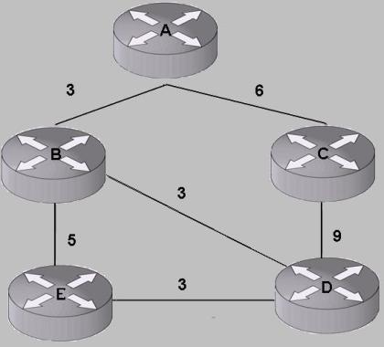
Imagine a simple network as shown in the figure below.

Network Diagram

Once each router has flooded its link state information in the network, all routers know about all the other routers and the links connecting them. The link state database on each router looks like the following:

[A, B, 3], [A, C, 6], [B, A, 3], [B, D, 3], [B, E, 5], [C, A, 6], [C, D, 9], [D, C, 9], [D, B, 3], [D, E, 3] , [E, B, 5] and [E, D, 3]

Each triple should be read as {originating router, router its connected to, the cost of the link connecting the two routers}

So what does Router A do with this information and how is this used in SPF?

While running SPF, each router maintains two lists – the first is a list of nodes for which the shortest path has been determined and we are sure that no path shorter than the one we have computed can exist. This list is called the PATH (or PATHS) list. The second is the list of paths through the routers that may or may not be the shortest to a destination. This list is called the TENTative list, or simply the TENT list From now on, TENT would refer to the TENT list and PATH, to the PATH list.

Each element in the list is a triplet of the kind {endpoint router that we’re trying to reach, total distance from the calculating router, next-hop to reach the endpoint router}

Each router runs the following algorithm to compute the shortest path to each node:

Step I: Put “self” on the PATH with a distance of 0 and a next hop of self. The router running the SPF refers to itself as either “self” or the root node, because this node is the root of the shortest-path tree.

Step II: Take the node (call it the PATH node) just placed on the PATH list and examine its list of neighbors. Add each neighbor to the TENT with a next hop of the PATH node, unless that neighbor is already in the TENT or PATH list with a lower cost.

Call the node just added to the TENT as the TENT node. Set the cost to reach the TENT node equal to the cost to get from the root node to the PATH node plus the cost to get from the PATH node to the TENT node.

If the node just added to the TENT already exists in the TENT, but with a higher cost, replace the higher-cost node with the node currently under consideration.

Step III: Find the lowest cost neighbor in the TENT and move that neighbor to the PATH, and repeat Step 2. Stop only when TENT becomes empty.

Lets follow the sequence that Router A goes through for building its SPF tree.

1st Iteration of the SPF run

Step I: Put “self” on the PATH with a distance of 0 and a next hop of self. After this step the PATH and TENT look as follows:

PATH – {A, 0, A}

TENT – { }

Step II: Take the node (call it the PATH node) just placed on the PATH list and examine its list of neighbors. Patently, A is the PATH node. Examine its list of neighbors ({A, B, 3}, {A, C, 6}). OSPF does this by looking at the LSAs advertised by Router A, while IS-IS does this by looking at the neighbors TLV found in Router A’s LSP. When an IS-IS node is placed in PATHS, all IP prefixes advertised by it are installed in the IS-IS Routing Information Base (RIB) with the corresponding metric and next hop.

The Step II further says – “Add each neighbor to the TENT with a next hop of the PATH node, unless that neighbor is already in the TENT or PATH list with a lower cost.” A’s neighbors are B and C, and since neither of them is in the PATH or TENT, we add both of them to the TENT.

PATH – {A, 0, A}

TENT – {B, 3, A}, {C, 6, A}

Step II says – “Call the node just added to the TENT as the TENT node. Set the cost to reach the TENT node equal to the cost to get from the root node to the PATH node plus the cost to get from the PATH node to the TENT node.”

Lets pick up the TENT node B. The cost to reach B would be the cost to reach from root node to PATH node + cost from PATH node to TENT node. In the first iteration of SPF, both the root node and PATH node is A. Thus total cost to reach B is cost to reach from A (PATH node) to B (TENT node) which is 3.

Step II says – “If the node just added to the TENT already exists in the TENT, but with a higher cost, replace the higher-cost node with the node currently under consideration.”

B isnt in the TENT, so skip this.

Step III says – “Find the lowest cost neighbor in the TENT and move that neighbor to the PATH, and repeat“. The lowest cost neighbor is B (with cost 3). Move this to PATH. We go back to Step II since TENT isnt yet empty.

2nd Iteration of the SPF run

PATH – {A, 0, A} {B, 3, A}

TENT – {C, 6, A}

We have thus added the neighbor B in PATH, since we know that there cannot be any other shorter path to reach it. And this is, as you will note, consistent with our definition of PATH wherein we had earlier stated that nodes can only be placed there once we are sure that there cannot be any shorter path to reach them from the root node.

We begin our 2nd iteration and go to Step II which says – “Take the node (call it the PATH node) just placed on the PATH list and examine its list of neighbors“. B is the PATH node and we examine its neighbors (A, E and D). Step II further says – “Add each neighbor to the TENT with a next hop of the PATH node, unless that neighbor is already in the TENT or PATH list with a lower cost.”

Since A is already in PATH with ignore it and only add E and D to TENT.

PATH – {A, 0, A} {B, 3, A}

TENT – {C, 6, A} {D, 3, B}, {E, 5, B}

Step II says – “Call the node just added to the TENT as the TENT node. Set the cost to reach the TENT node equal to the cost to get from the root node to the PATH node plus the cost to get from the PATH node to the TENT node.

Aah .. this means that cost against D and E would not be 3 and 5, as what i have shown, but would instead be 3 (cost from A to B) +3 (cost from B to D) = 6 and 3 (cost from A to B) +5 (B to E) = 8

Thus the PATH and TENT look as follows:

PATH – {A, 0, A} {B, 3, A}

TENT – {C, 6, A} {D, 6, B}, {E, 8, B}

The rest of the Step II does not apply here since D and E dont exist in the TENT.

Come to Step III which says “Find the lowest cost neighbor in the TENT and move that neighbor to the PATH, and repeat Step 2″.

Lowest cost neighbor can either be C or D so pick on up randomly. It can mathematically be proven that we would end up with the same SPF tree irrespective of which equal cost neighbor is picked up from the TENT first. In our case, lets pick up C.

It is thus moved to the PATH

PATH – {A, 0, A} {B, 3, A} {C, 6, A}

TENT – {D, 6, B}, {E, 8, B}

3rd Iteration of the SPF run

Go back to Step II which says “Take the node (call it the PATH node) just placed on the PATH list and examine its list of neighbors. Add each neighbor to the TENT with a next hop of the PATH node, unless that neighbor is already in the TENT or PATH list with a lower cost

C’s neighbors are A and D. Since A is already in the PATH only D is added in the TENT.

PATH – {A, 0, A} {B, 3, A} {C, 6, A}

TENT – {D, 6, B}, {E, 8, B} {D, 9, C}

As per Step II we now need to fix the cost to reach D from the root node. This would be cost to reach from A to C (6) + cost from C to D (9) = 15

PATH and TENT now:

PATH – {A, 0, A} {B, 3, A} {C, 6, A}

TENT – {D, 6, B}, {E, 8, B} {D, 15, C}

Step II further says – “If the node just added to the TENT already exists in the TENT, but with a higher cost, replace the higher-cost node with the node currently under consideration.

node D already exists in the TENT (via B with cost 6) and since its with a lesser cost, we remove the node that we had just added from the TENT. This is because a lower cost path to reach node D already exists in the TENT.

PATH – {A, 0, A} {B, 3, A} {C, 6, A}

TENT – {D, 6, B}, {E, 8, B}

We come to Step III which says “Find the lowest cost neighbor in the TENT and move that neighbor to the PATH, and repeat Step 2″.

Lowest cost neighbor is D – which means we move D now to the PATH and go to Step II, since the TENT isnt yet empty.

4th Iteration of the SPF run

PATH – {A, 0, A} {B, 3, A} {C, 6, A} {D, 6, B}

TENT – {E, 8, B}

Step II says “Take the node (call it the PATH node) just placed on the PATH list and examine its list of neighbors. Add each neighbor to the TENT with a next hop of the PATH node, unless that neighbor is already in the TENT or PATH list with a lower cost.”

To examine D’s neighbors we look at the link state information it advertised. It advertised the following information:

[D, C, 9], [D, B, 3], [D, E, 3]

This means that D is says that its connected to C, B and E. We ignore its connection to B and C, since they are already in PATH. We thus only add neighbor E in the TENT.

PATH – {A, 0, A} {B, 3, A} {C, 6, A} {D, 6, B}

TENT – {E, 8, B} {E, 3, D}

Continuing with Step II which further says – “Call the node just added to the TENT as the TENT node. Set the cost to reach the TENT node equal to the cost to get from the root node to the PATH node plus the cost to get from the PATH node to the TENT node.”

This means that we need to adjust the cost of the triple {E, 3, D} that we just added to the TENT. The cost to reach E via D would thus be the cost to reach D from A (which is the root node) + the cost to reach E from D. This comes out to be 6 + 3 = 9.

TENT thus looks like this – {E, 8, B} {E, 9, D}

Step II further says – “If the node just added to the TENT already exists in the TENT, but with a higher cost, replace the higher-cost node with the node currently under consideration”

We just added node E in the TENT and a route to E already exists in the TENT, and its with a lower cost. This means that we remove the route that we had just added.

So PATH and TENT at this point look as follows:

PATH – {A, 0, A} {B, 3, A} {C, 6, A} {D, 6, B}

TENT – {E, 8, B}

We go to Step III which says – “Find the lowest cost neighbor in the TENT and move that neighbor to the PATH, and repeat Step 2″.

The lowest cost neighbor in TENT right now is E. We move this to PATH.

So PATH and TENT at this point look as follows:

PATH – {A, 0, A} {B, 3, A} {C, 6, A} {D, 6, B} {E, 8, B}

TENT – { }

Step III further states that we continue if and only if something remains in the TENT. TENT is now empty, which means that we have computed the shortest paths to all the nodes that A was aware of.

This is marks the end of the SPF algorithm run and the SPF tree that it has computed looks as follows

Network Topology after the SPF Run

Shortest Path First (SPF) Calculation in OSPF and IS-IS

Both OSPF and IS-IS use the Shortest Path First (SPF) algorithm to calculate the best path to all known destinations based on the information in their link state database. It works by building the shortest path tree from a specific root node to all other nodes in the area/domain and thereby computing the best route to every known destination from that particular source/node. The shortest path tree thus constructed, consists of three main entities – the edges, the nodes and the leaves.

Each router in OSPF or an Intermediate System in case of IS-IS, is a node in the SPF tree. The links connecting these routers, the edges. The IP network associated with an IP interface, added into OSPF via the network command is a node, while the IP address associated with an interface thats added in IS-IS is  a leaf. An IP prefix redistributed into OSPF or IS-IS from other routing protocols (say BGP)  becomes a leaf in both the protocols. Inter-area routes are patently, the leaves.

Network Diagram

If you consider the network as shown above, then OSPF would consider routers A, B, C and the network 10.1.1.0/24 as nodes. This is assuming that the interface associated with 10.1.1.0/24 has been added into OSPF. The only leaf in the graph would be the IP prefix 56.1.1.0/24 redistributed into A from some other protocol. IS-IS otoh, would consider routers A, B and C as nodes and networks 10.1.1.0/24 and 56.1.1.0/24 as leaves. This seemingly innocuous difference in representation of the SPF tree leads to some subtle differences between the SPF run in OSPF and IS-IS, which can interest a network engineer.

The nodes in the shortest path tree or the graph form the backbone or the skeleton of that tree. Any change there necessitates a recalculation of the SPF tree, while a change in a leaf of the SPF tree does not require a full recalculation. Removing and adding of leaves without recalculating the entire SPF tree is known as Partial SPF and is a feature of almost every implementation of OSPF and IS-IS that i am aware of. This implies that if the link connecting router C to 10.1.1.0/24 goes down, then a full SPF would be triggered in case of OSPF, and a partial SPF in case of IS-IS.

This shows that the general adage – “Avoid externals in OSPF” should be taken with a pinch of salt and it really depends upon your topology. I have seen networks where ISPs redistribute numerous routes that have a potential to change on a regular basis, as opposed to bringing them via the network command.

IS-IS

o IP routing is integrated into IS-IS by adding some new TLVs which carry IP reachability information in the LSPs. All IP networks are considered externals, and they always end up as leaf nodes in the shortest path tree when IS-IS does a SPF run. All node information, neccessary for SPF calculation is advertised in its IS Neighbors or IS Reachability TLVs. This unambiguously separates the prefix information from the topology information which makes Partial Route Calculation (PRC) easily applicable. Thus IS-IS performs only the less CPU intensive PRC when network events do not affect the basic topology but only affect the IP prefixes.

o Used narrow (6 bits wide) metrics which helped in some SPF optimization. However such small bits proved insufficient for providing flexibility in designing IS-IS networks and other applications using IS-IS routing (MPLS-TE). “IS-IS extensions for Traffic Engineering” introduced new TLVs which defined wider metrics to be used for IS-IS thus taking away this optimization. But then CPU are fast these days and there arent many very big networks anyways!

o SPF for a given level is computed in a single phase by taking all IS-IS LSP’s TLV’s together.

OSPFv2

o Is built around links, and any IP prefix change in an area will trigger a full SPF. It advertises IP information in Router and Network LSAs. The routers thus, advertise both the IP prefix information (or the connected subnet information) and topology information in the same LSAs. This implies that if an IP address attached to an interface changes, OSPF routers would have to originate a Router LSA or a Network LSA, which btw also carries the topology information. This would trigger a full SPF on all routers in that area, since the same LSAs are flooded to convey topological change information. This can be an issue with an access router or the one sitting at the edge, since many stub links can change regularly.

o Only changes in interarea, external and NSSA routes result in partial SPF calculation (since type 3, 4, 5 and 7 LSAs only advertise IP prefix information) and thus IS-IS’s PRC is more pervasive than OSPF’s partial SPF. This difference allows IS-IS to be more tolerant of larger single area domains whereas OSPF forces hierarchical designs for relatively smaller networks. However with the route leaking from L2 to L1 incorporated into IS-IS the apparent motivation for keeping large single area domains too goes away.

o SPF is calculated in three phases. The first is the calculation of intra-area routes by building the shortest path tree for each attached area. The second phase calculates the inter-area routes by examining the summary LSAs and the last one examines the AS-External-LSAs to calculate the routes to the external destinations.

o OSPFv3 has been made smarter. It removes the IP prefix advertisement function from the Router and the Network LSAs, and puts it in the new Intra-Area Prefix LSA. This means that Router and Network LSAs now truly represent only the router’s node information for SPF and woudl get flooded only if information pertinent to the SPF algorithm changes, i.e., there is atopological change event. If an IP prefix changes, or the state of a stub link changes, that information is flooded in an Intra-Area Prefix LSA which does not trigger an SPF run. Thus by separating the IP information from the topology information, we have made PRC more applicable in OSPFv3 as compared to OSPF2.

I recently wrote a post that discusses this further.

Issues with existing Cryptographic Protection Methods for Routing Protocols

Most of us believe that using cryptographic authentication methods (MD5, etc) for the routing protocols running inside our networks really makes them very secure. Well, not really ..

We have published RFC 6039 that explains how each routing protocol can be exploited despite using the cryptographic authentication mechanisms endorsed by the IETF community.

To cite an example, a simple IP header attack on OSPF or RIP can result in the two adjacent routers bringing down the peering relationship between them. This can, in the worst case, blackhole a substantial amount of data traffic inside the network, something that will certainly not go well with the customers!

So how can an OSPF adjacency be brought down?

OSPF neighbors on the broadcast, NBMA and point-to-multipoint networks are identified by the IP address in the IP header. Because the IP header is not covered by the MAC in the cryptographic authentication scheme as described in RFC 2328, an attack can be made exploiting this vulnerability.

R1 sends an authenticated HELLO to R2. This HELLO is captured and replayed back to R1, changing the source IP in the IP header to that of R2.

R1 not finding itself in HELLO would deduce that the connection is not bidirectional and would bring down the adjacency!

The RFC also discusses some issues that we found with Bidirectional Forwarding Detection (BFD) protocol thats very frequently used in the service provider networks.

Graceful Restart Mechanisms in OSPF and IS-IS ..

If the control and forwarding functions in a router can be separated independently, it is possible to maintain a router’s data forwarding capability intact while the router’s control software is restarted/reloaded. This functionality is termed as “graceful restart” or “nonstop forwarding”.  The router’s control software (the routing protocols and the signalling protocols) can stop and can restart for myriad reasons – SW error crashing the protocol task, a switchover to the redundant control card, or a planned shutdown as part of the operational maintenance – the list is endless. The idea behind graceful restart is to continue forwarding packets based on the snapshot of FIB just before the router restarted. The restarting router is assumed to be capable of preserving the FIB and some amount of control information (like cryptographic sequence number in case of OSPF).

OSPF

o Restarting OSPF router originates a Grace LSA (link local Opaque LSA)  specifying the ‘grace period’, thereby indicating to its neighbors the time, in seconds, that the neighbors (the helpers)  should continue to consider this router as fully adjacent. The helping neighbors enter into a state known as helping mode during this period. The onus falls on the helpers to detect a topological change during the grace period and acting accordingly.

o  In case of a planned restart, OSPF issues a Grace LSA to its neighbors on each restarting interface and sets the value 1, which is Software restart, in the Graceful Restart Reason TLV. In case of an unplanned outage, the router first issues a Grace LSA before sending out any HELLOs. Most implementations transmit the Grace LSAs multiple times, till an acknowledgement is heard from the neighboring routers.

o The helping router continues advertising the restarting router in its LSAs and other routers in the network never come to know of this event.

o Using standard OSPF procedures the helping routers establish adjacencies with the restarting router and synchronize their LSDBs. During the grace period, the restarting router receives its own self generated pre-restart LSAs. It accepts them as valid, and does not originate type 1 through 5 and type 7 LSAs, even after it transitions to a FULL state. The restarting router can run the SPF, but its not yet allowed to update the FIB.

o Once the restarting router and its helpers have synchronized their databases within the grace period, the former flushes its grace LSAs to signal successful completion of the gracweful restart procedure. The restarting router now reoriginates its router LSAs on all attached areas and the network LSAs on the segments, where its the DR. It now schedules a full SPF, calculates the routes, and updates the FIB.

o The restarting router had marked all the routes in FIB as stale before sending out the Grace LSAs. After graceful restart is over and it has recalculated the routes, it deletes all the routes marked as stale in the FIB. It can now reoriginate summary LSAs, type 7 LSAs and AS External LSAs as appropriate.

o When the helpers receive the flushes Grace LSAs, they exit the helper mode and revert back to normal OSPF procedures.

o OSPF automatically reverts back to standard OSPF restart from graceful restart if topological changes are detected or if one or more of the restarting router’s neighbors do not support graceful restart.

o More details here.

IS-IS

o Restarting router does not re-compute its own routes until it has achieved database synchronization with its neighbors.

o Uses restart TLV (type 211) in its IIH to obtain the graceful restart functionality. Grace period is decided as the minimum of the Remaining times of received IIHs containing a restart TLV with RA bit set.  Upon receiving this IIH, the helping routers would flood the complete sets of CSNPs onto the link and set the SRM flag on all its LSPs towards the restarting router.

o The restarting router can now clear its restart timer, since it has some helping routers that can provide a full set of link state information through the normal transmission and retransmission process.

o  During grace period, restarting router does not transmit self-originated LSPs and self-LSPs are not purged or modified. These restrictions are necessary to prevent premature removal of an own LSP and hence churn in other routers.

o Restart mechanism in IS-IS allows to establish adjacency without cycling through the normal operation of adjacency state machine.

o If a timer on the restarting router expires before it recieves a full set of CSNPs from its helpers, the adjacency is reset, and a normal neighbor restart is attempted.

o  Usual database synchronization is achieved in situations where the neighboring routers of the restarting router do not support the restart TLV.

o More details here.

Metrics Size in OSPF and IS-IS ..

Each interface in the link state protocols in given a metric or a cost, which is advertised with the link state information in the LSP or the LSA. The SPF algorithm uses this metric to calculate the cost and the nexthop to a destination. Metrics used are generally the inverse of bandwidth, thus a large bandwith capacity link would have a lower metric

IS-IS

o ISO10589 specified the metric to be 6 bits in size. Therefore, the metric value could only range from 0-63. This metric information was carried in Neighbor Reachbility TLV and the IP reachability TLV. Since it was only 6 bits wide, it was called the “narrow metric“. The maximum path metric MaxPathMetric supported is 1023. This in theory brought down the complexity of the SPF algorithm from O(nlog n) to O(n). But this isn’t a significant motivation any more since the CPUs are really fast these days. The metric size apparently was kept small to optimize search while doing the SPF. It also allowed two types of metrics – External and Internal.

o Soon , the “narrow” metric range was found to be too small for certain networks and new TLVs (Extended IP and Extended Neighbor Reachability) were introduced to carry larger metrics as part of the Traffic Engineering document. These were called Wide Metrics. The MaxLinkMetric value now is 0xFFFFFFand the MaxPathMetric, 0xFE00000.

The Extended IP reachability TLV allows for a 4 byte metric, while the Extended Neighbor reachability TLV allows for 3 bytes metric size. This is to enable the metric summarized across levels/domains to be as large as 0xFFFFFFFF while the link metric itself is no larger than 0xFFFFFE. If a metric value of 0xFFFFFF is used the prefix is not used in SPF computation.

o The original specification defined 4 kinds of narrow metrics – delay, default, error and expense. These were never implemented and all implementations only support the default metric. In ISO 10589, the most significant bit of the 8 bit metrics was the field S (Supported) which defined if the metric was to be considered or not. Confusingly, as most ISO documents are, an implementation was supposed to set this bit to 1 if it wanted to indicate that the metric was unsupported. Since only the default metric is used, the implementations must always set this bit to 0 when using the narrow metrics. Later RFC 2966 used this bit in the default metric to mark L1 routes that have been leaked from L1 to L2 and back down into L1 again.

Current implementations must generate the default metric when using narrow metrics and should ignore the other three metrics when using narrow metrics.

OSPFv2

o It allows a link to have a 2 byte metric field in the Router LSA which implies a maximum metric of 0xFFFF.

o The Summary, Summary ASBR, AS-External and NSSA LSAs have a 3 byte metric value. A cost of 0xFFFFFF (LSInfinity) is used to tell the destination described in the LSA is unreachable.

o AS-External and NSSA LSAs allow two metric types, Type 1 and Type 2 which are equivalent to IS-IS Internal and External metrics. The type 1 considers the cost to the ASBR in addition to the advertised cost of the route while the latter uses just the advertised cost while calculating the routes during the SPF.

o The scheme thus allows for links to be configured with a metric no larger than 0xFFFF, while allowing cost of destinations injected across areas/levels to be as large as 0xFFFFFE.

OSPFv3

o It allows similar metric size for the Router LSA as in OSPFv2.

o It allows similar metric sizes for Intra Area Prefix LSA, Inter Area Prefix LSA, AS-External LSA and NSSA LSA as in OSPFv2. The value and significance of LS Infinity is valid here too.

Packet Alignment and Extensibility Issues in OSPF and IS-IS

IS-IS

o Does not require any particular alignment of the PDU fields.

o Uses Type-Length-Value (TLV) encoded packets to advertise the routing information. The TLVs that are not supported/recognized are ignored by other IS-IS routers.

o LSPs are flooded intact with unrecognized TLV information making it very extensible. IPv6, GMPLS, etc. support is provided by simply adding a few more TLVs.

o TLVs can be nested as sub-TLVs providing even more flexibility for future extensions. Though the base spec does not use them but the newer drafts and RFCs have started using them (TE extensions, etc).

OSPFv2

o Uses fixed format packets with all fields aligned at 32-bit boundaries for faster processing of the OSPF packets (doesn’t really matter anymore as the CPUs are really fast these days!). This was primarily done because OSPF was meant to be an IPv4 only protocol.

o The downside of the above is that the packet formats are not at all extensible. We had to come out with OSPFv3 when we wanted to provide support for IPv6.

o It uses Link State Advertisements (LSAs) for advertising the routing information and the original specification called for dropping any unrecognized LSA type.

o LSAs of type 9, 10 and 11 have been introduced for advertising other application specific information and enough vendors now support this so that they are likely to get from one side of the network to the other.

o Since the unrecognized LSA types are not flooded to neighbors it makes it very difficult to extend OSPF. This in turn means that all the OSPF routers must be upgraded network-wide to make the new extensions work.

o The new RFCs (Traffic Engineering, GMPLS extensions, etc) written for OSPF now support TLV encoding.

OSPFv3

o Exhibits implicit opaque LSA behaviour i.e. unrecognized LSA types are flooded to the neighbors making it more extensible that OSPFv2

o Designed in a way which makes it easily extensible to any other layer 3 protocol suite.

Convergence and Scalability Issues in OSPF and IS-IS

This seems to be the favorite question that every newbie has! There is no unequivocal answer to this and it all depends upon the kind of network and the topology. Having said this, lets try to see how the two IGPs can be compared.

IS-IS

This protocol is limited by the maximum number of LSPs that each IS-IS router can issue. This is 256 as its LSP ID is 1 octet long. The total number of IP prefixes carried by IS-IS can be easily computed and it comes to O(31000). However, RFC 3786 describes mechanisms to relax the limit on the number of LSP fragments, thereby increasing the number of IP prefixes that can be carried within IS-IS.

I have however, never seen any network carrying more than O(30K) IP prefixes inside IS-IS. Do let me know if you’re aware of networks where you see IS-IS carrying more than 30K routes.

I say this because this is a reasonable number for any sane IS-IS deployment and it will not run out of space unless someone actually injects the entire (or even partial) BGP feed into the IGP. In that case we will run out of space at about 20% of the way into redistribution and not be able to advertise the rest. It is for this reason that this practice has now been deprecated and the RFC 1745 which lays down the rules for BGP- OSPF interaction, has been moved to the HISTORICAL status.

There are 8 bits to define a pseudonode number in the LSPID which means that a router can be a Designated Intermediate System (DIS) for only 256 LANs. Additionally there is also a limitation on the number of routers that can be advertised in pseudonode LSP of the DIS. Dont worry – RFC 3786 fixes this!

RFC 3373 OTOH proposes a new TLV thats carried in the IIH PDUs that can increase the number of point-to-point adjacencies from 256 on a single router.

The “Remaining lifetime” field which gives the number of seconds before LSP is considered expired is 16 bits wide.

This gives the life time of the LSP as 2^16/60/60 Hrs = 18.7 Hrs

Thus the LSP issued by a router needs to be refreshed after every 18.7 Hrs. So youre not going to see a lot of IS-IS control packets being regenerated in a stable topology.

OSPF

In theory, OSPF topology is limited by the number of links that can be advertised in the Router LSA as each router gets only one Router LSA and it cant be bigger than 64K which is the biggest an IP packet can be. The same constraint applies to the Network LSA also.

Each link in the router can take up at most 24 bytes. Thus, number of links which can be supported is given by (64 * 1024) / 24 = 2370

However, if we take the minimum link size per link (12 bytes) then the maximum is about 2 * 2370 = O(5000) links

To be more specific, we can have O(2300) p2p and p2mp links (not considering virtual links, etc) and O(5000) broadcast/NMBA links described in OSPF’s Router LSA and its Network LSA.

Thus each Router LSA can carry some 5000 links information in it. It is hard to imagine a router having 5000 neighbors but there are already routers with 400 neighbors in some ISPs, and it may not take long to reach the order of the magnitude limited by OSPF.

The Network LSAs are generated by the designated router (DR) for each broadcast network it is connected to. To have scaling problems it should have 2730 * 6 times neighbors on that interface. This is even less probable and hence there are no scalability problems with OSPF per se.

All other LSAs apart from Type 1 and Type 2 hold single prefixes. Because there is no limit to the number of such LSAs, a large number of inter-area and externals can be generated depending upon the memory resources of the router.

Each LSA has an LS Age field which is counted upwards starting from zero. Its life is an architectural constant which says one hour. When an LSA’s LS age field reaches MaxAge, it is reflooded in an attempt to flush the LSA from the routing domain. One hour seems like a long time but if one originates 50,000 LSAs then OSPF will be refreshing on an average of just 36ms!

Total number of LSAs to be refreshed = 50,000

Time by which all the LSAs must be refreshed = LSRefreshTime = 30mins = 1800 secs

Rate at which the LSAs need to be refreshed = 1800/50000 = 36ms

However, if the refreshes are perfectly spread out across time and perfectly batched, the actual update transmission rate may be on the order of one packet per second.

There is however a “do-not-age” LSA which in theory can be pressed into service and which never gets aged. However, such LSAs will be eventually purged from the LS database if they become stale after being held for at least 60 minutes and the originator not reachable for the same period. Moreover it is not backward compatible and if one deploys that in the network today with some routers not supporting this then the network can really get weird. So there isn’t really much that can be done using these unless the whole network is changed!

Theoretically, both the routing protocols are scalable and there should not be any issues with either one of these if implemented properly. Both have similar stability and convergence properties. Practically, providers must go with what their vendors suggest since the vendors are best aware of how each protocol has been implemented on their platforms.

I discuss more of this here.

Database Granularity in OSPF vs IS-IS ..

This post compares how the two link state protocols hold their routing information in their databases as this affects their behavior in how they flood/distribute the change of routing information and the internal implementation complexity.

OSPF

o Organization of Routing Information

OSPF encodes the routing information into small chunks, which it calls Link State Advertisement (LSA). Each LSA has its own 20-byte header in order to be identified uniquely. This header is called the LSA Header. There is no limitation on the size of a LSA, though the actual LSA size is limited by IP packet size limitation: 65,535 bytes minus the LSA Header size and IP packet header size. The database access in OSPF is per LSA basis.

In OSPF routing, the information within an area is described by type 1 and type 2 LSAs (known as Router-LSA and Network-LSA respectively). These LSAs can become big depending upon the number of adjacencies to be advertised and prefixes to be carried inside an area. In other words, the routing information with respect to a single node (either router or network node) is encoded inside a single LSA. On the other hand, each inter-area or external prefix is advertised in a separate LSA (AS-External LSA).

An OSPFv2 router may originate only one Router-LSA for itself, while in OSPFv3, a router is allowed to originate multiple Router-LSAs. A router may originate a Network-LSA for each IP subnet on which the router acts as a designated router (DR). A router may originate one LSA for each inter-area and external prefix, with no limitations on the number of LSAs that it may originate.

Consequences

Originating a new and a unique LSA for each inter-area route and an external prefix implies that there is a LSA Header overhead involved while the information is kept in the database or is flooded to the neighbors. There is thus some extra memory and bandwidth consumed in total.

o Carrying Routing Information

LSAs are carried in Link State Update packets (called LS Updates or LSUs). Each LS Update packet has its own header, consists of a 24 byte OSPF protocol header, and a 4-bytes field indicating the number of LSAs contained in the packet. Thus multiple LSAs can be packed into a single LS Update packet. Some implementations may not do this as its considered difficult achieving this during flooding.

Consequences

In the face of network changes, OSPF floods only the updated LSAs. Therefore, even if an implementation does not pack multiple LSAs into a single LS Update packet (and so bandwidth is consumed by LS Update header for each update of a single LSA), the bandwidth consumption for each network change can be considered adequately small.

IS-IS

o Organization of the Routing Information

In IS-IS, protocol packets are called Protocol Data Units or PDUs. IS-IS encodes the link state information into the set of TLVs and packs these TLVs into one or more Link State PDUs (LSPs). The size limit of a LSP is configurable. The Routing database consists of these PDUs and the access to the database is per PDU basis. The original IS-IS specification places an upper bound on the number of LSPs a router can originate to 255. There are however techniques which enable a router to originate more than 255 LSPs, by using multiple system-id’s for itself.

Consequences

Since routing information in IS-IS for each router is packed in fewer LSPs, the memory consumed for bookkeeping of the routing data within the database is less and is more efficient.

o Carrying Routing Information

Each LSP is flooded independently, without being modified all the way from the originator through the routers till the very end. This results in all the routers having the same LSPs as that originated by the first router.

Consequences

Since LSPs are not modified in any way and are not allowed to be fragmented, in order to be flooded successfully over all links existing in the IS-IS network, great care must be ensured when configuring the size limit of LSP that routers can originate and receive.

If the size limit of the LSP is set without taking into account the minimum value of the MTUs throughout the network, or if the size limit of LSPs conflict among some the routers in the network, the database synchronization may not be achieved, and this can result in routing loops and/or blackholes.

When a change occurs to a LSP, the whole LSP needs to be flooded, and therefore the bandwidth usage can be non-optimal. There is however a solution which exists in theory. If an implementation finds some of the entities to be flapping, then they may be packed into smaller LSPs or may be isolated from the other stable entities. This way one needs to only advertise the unstable LSP/LSPs. I have not btw come across any implementation that does that. Leave a comment if you know one that does this!

Database granularity also affects when two routers need to synchronize their databases. In OSPF, because of its high database granularity there are a lot of items which it needs to synchronize and that process is somewhat complicated with a lot of DBD packets being exchanged back and forth. This gets worse if the router trying to sync is being inundated with a lot of other data traffic also. This is not much of an issue these days as any router worth its salt would prioritize the OSPF control packets.

This is however much simpler in case of IS-IS and there isn’t any finite state machine that the neighbors need to go through to synchronize their databases. It just uses it regular flooding mechanism (a couple of CSNPs describe their entire topology information) to exchange its entire database. You plug in the new IS-IS router and before you realize the router is already sync’ed up with all the other IS-IS routers in the network!

Checks on HELLOs for OSPF and IS-IS during Adjacency Formation ..

The HELLOs (or IIHs in IS-IS parlance)  are responsible bringing up the adjacencies between the two (or multiple) routers. Forming adjacencies is an integral part of all link state routing protocols as all protocol packets other than HELLOs are flooded only over the adjacencies. The rules for formation of such adjacencies however differ between IS-IS, OSPF v2 and OSPF v3.

IS-IS

Besides the basic checks to verify the integrity of the packet, IS-IS does a few checks before forming any adjacency upon receiving the IIHs.

o It allows multiple area addresses to be configured on a router. During the IIH exchange the adjacency is formed only if at least one of the area address matches. The advantage of having multiple areas is explained in the further posts. NOTE that Level 2 only adjacencies would be formed even if the area addresses are not matching.

o To prevent the LSPs and CSNPs from being dropped due to different values for originatingLSPBufferSize and ReceiveLSPBufferSize, all IIHs are padded till the maximum MTU when the adjacency comes up. This check verifies consistent settings between the adjacent routers. This is however not a sufficient check.

o Adjacencies are formed without regard to interface addressing or asymmetric HOLD timer values. Values of IIH interval are not sent in IIH packets. While the IS-IS protocol provides sufficient routing information for relaying packets between adjacent routers, many implementations nonetheless require ARP support to do this. These implementations typically refuse to form an adjacency unless the neighbor interface IP address is on the local interface’s IP subnet.

o IS-IS can carry addressing information of different protocols in its TLV’s. However, the protocol supported field must be sent in Dual and IP-Only routers. RFC1195 specifies no checks for the protocol supported field for adjacency formation. It places topology restrictions on multi-protocol networks. In networks that conform to these restrictions, neighboring routers will always have a protocol in common. Therefore, it does not state whether adjacency formation should take protocols supported into account. However, many implementations, do not form an adjacency with a neighbor unless they share at least one protocol in common.

o Not matching Hold Timer values has advantages wherein the administrator can set different Hold times for different routers. This helps in cases where the going down of a DIS or some router needs to be detected faster. For such routers the hold timer can be set to a lower value.

OSPFv2

The checks for formation of adjacencies are stricter in OSPFv2 as compare to that of IS-IS.

o The area-id of the received packet should always match the incoming interface (with the exception of virtual links). Area type is strictly checked by checking the E-bit (not set for non-default areas) and the N- bit (not-set for non-NSSA areas).

o The values of the Hello interval, the Router Dead Interval and network mask received in Hellos are matched with those on the configured interface. Any mismatch in the values causes the Hello packet to be dropped and hence prevents formation of adjacencies. The disadvantage of this approach is that Hello Interval and Router Dead Interval changes need to be done within the Router Dead Interval, to prevent breaking adjacencies. The advantage is we would not form adjacency in case there is a router that has been mis-configured with a large value and which could cause problems later. The network mask check however does not apply to point to point links. That allows the two ends of a Point-to-Point link to have different addresses.

o MTU check is not done in the hellos. It is done in the during the Database (DB) Exchange process.

OSPFv3

Most of the checks for OSPFv3 are similar to that of OSPFv2.

o OSPFv3 runs on a per link basis instead of a per subnet basis. The check for a network mask is thus not done.

o Instance ID field (non-existent in OSPFv2) on the link is matched with the incoming ID in Hellos. The adjacency is formed only if the Instance ID matches. This allows multiple instances of OSPFv3 to run on a single link.